Where biology, physics and coding are works of art.
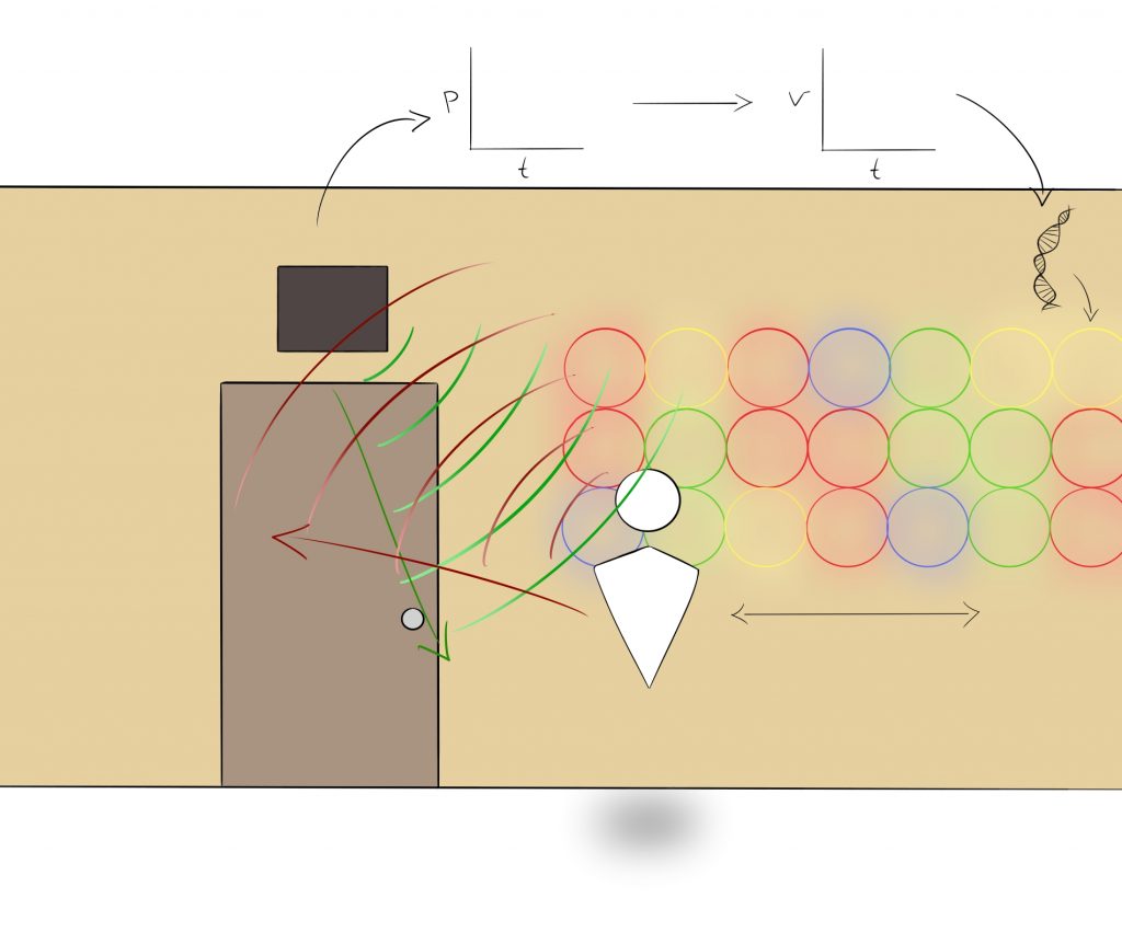
What if there was a mural of LED rings representing DNA that would change colours and simulate scrolling through a DNA sequence for a protein based on the movement of students in the hallway?
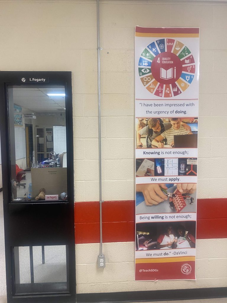
Society in the 4th Industrial Revolution will need students who are practiced at creative problem solving, which requires a diverse set of experiences from which non-obvious connections can be made. We need to showcase science as a dynamic, iterative process on the edge of the unknown rather than a series of already known facts, already solved problems and replicated lab reports. We can learn so much from the process of Art where they live on the ed ge, try something, fail, reconsider, gather inspiration from diverse experiences and redraw. The students of the 4th Industrial Revolution need a renaissance education that would make Da Vinci proud.
STEAM vs S.T.E.M There has been a movement to shift from S.T.E.M. to S.T.E.A.M. and I suggest we need to move beyond the period-punctuated silos, continue along the spectrum to the word, “STEAM.” There are too many examples of teachers trying to “put the ‘A’ in STEAM,” who often think of the Arts as a way to qualify a STEM project for grant funding: an add on at the end, to decorate or beautify a STEM project. DNArt hopes that the Science, technology and art are intertwined and interdependent. We have failed if the project does not collapse without one of the elements. In true STEAM pedagogy, the meaning is completely different when one letter is de-emphasized.
HMWE: How might we engage students in my physics class who have a love of biology or computer science in an iterative, problem solving artistic process that involves my physics curriculum? Because of their future paths, many different kinds of students find themselves in my class. It is a good thing for the development of young minds to practice thinking in a logical, computational way, to think spatially, to think about biological processes and to do it in a way that challenges their creativity, communication, collaboration and “stick-to-it-ness”.
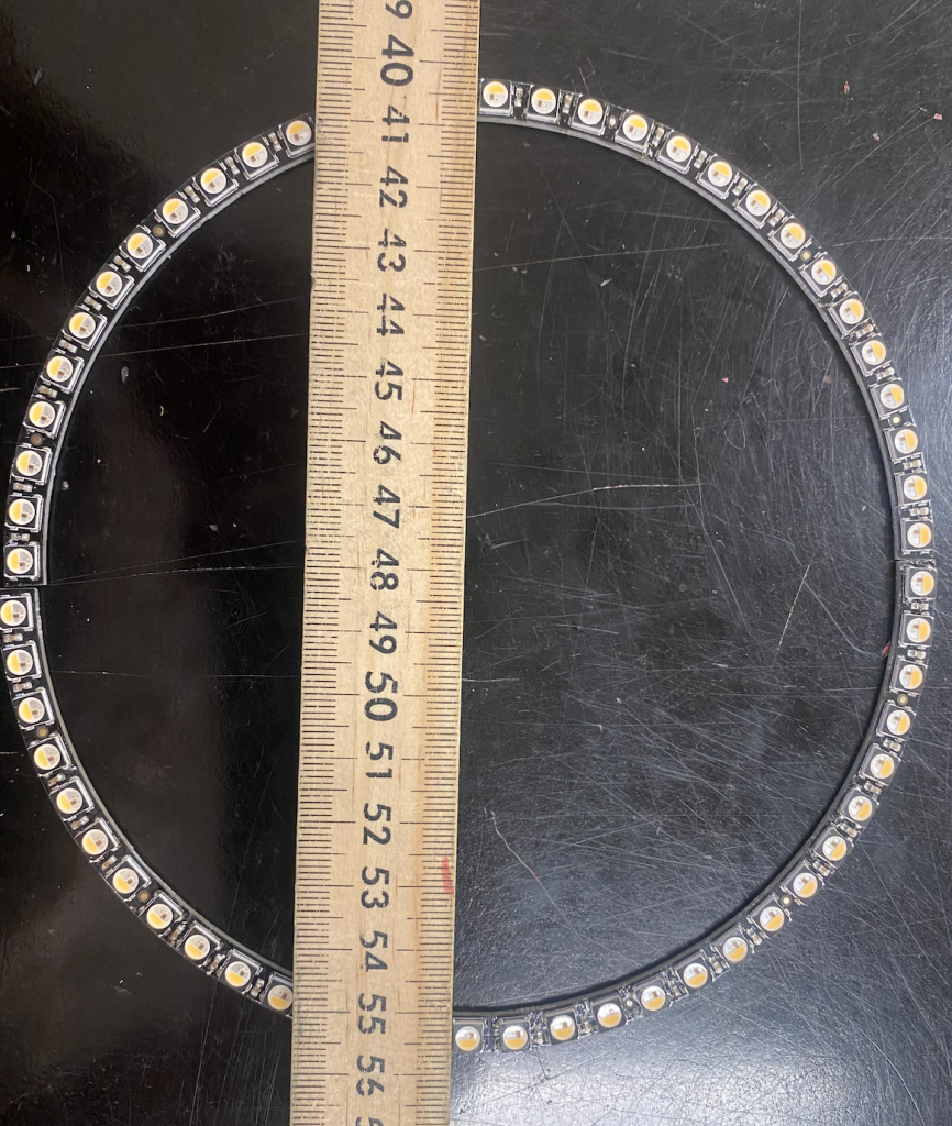
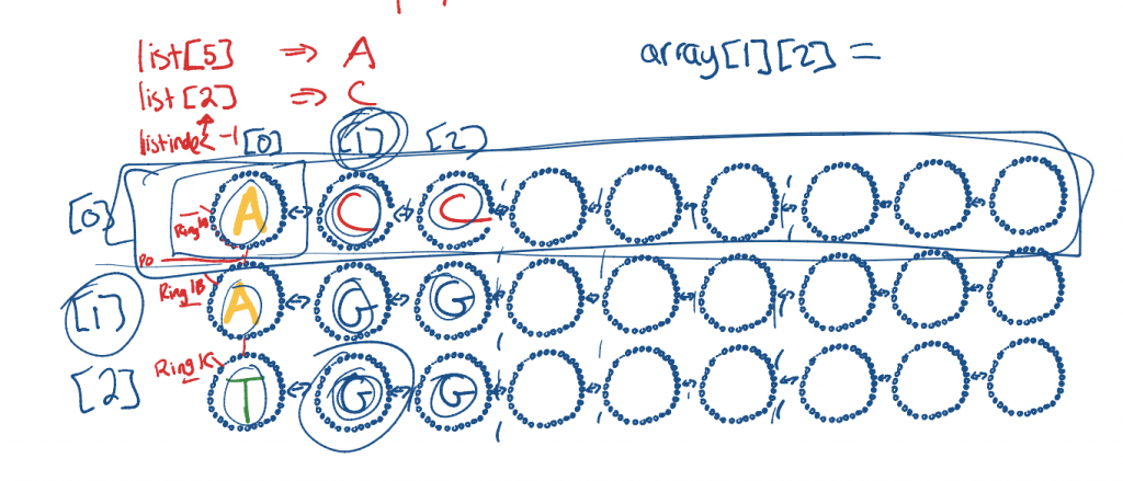
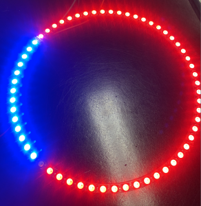
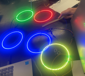
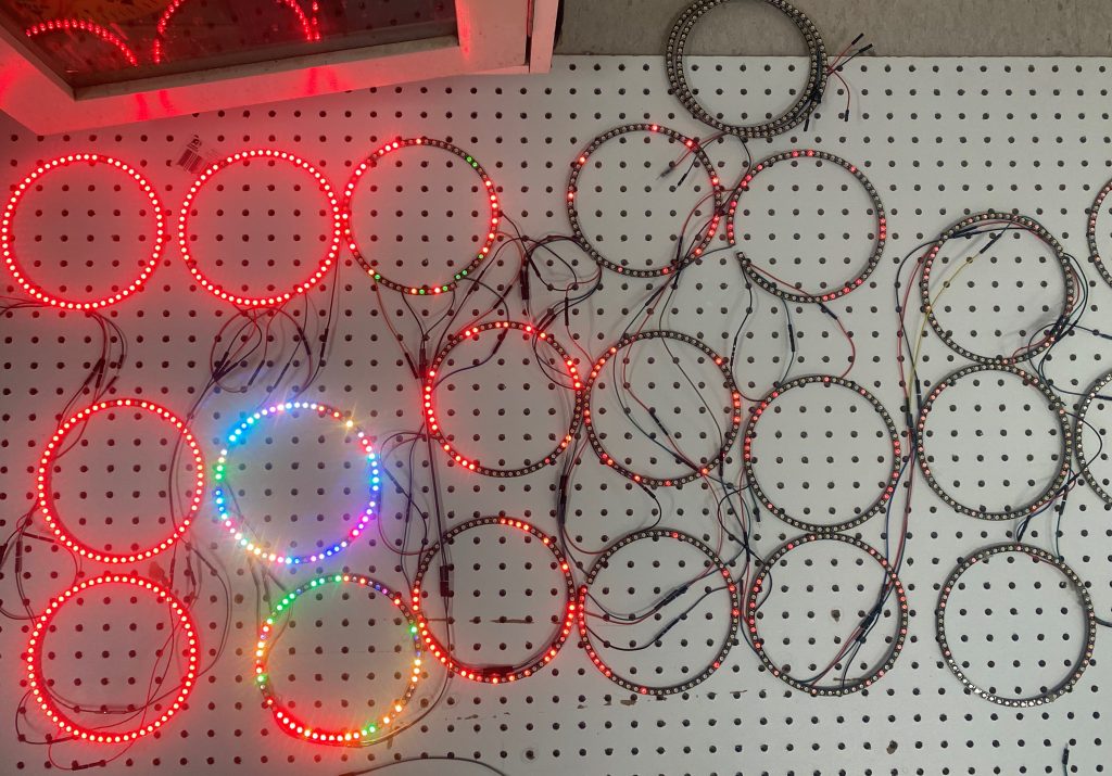
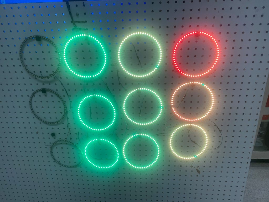
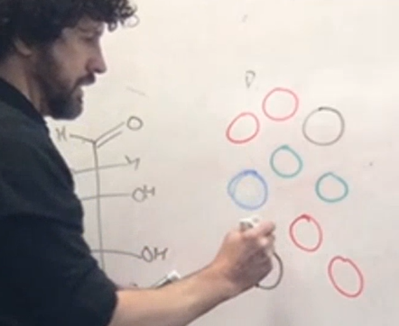
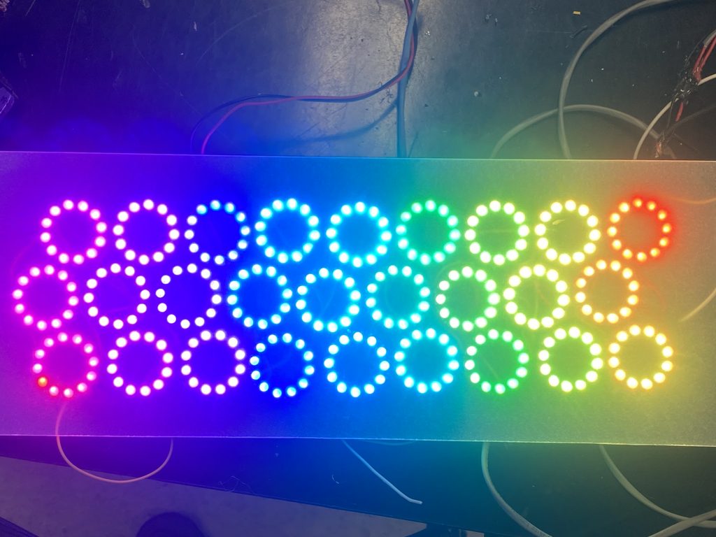
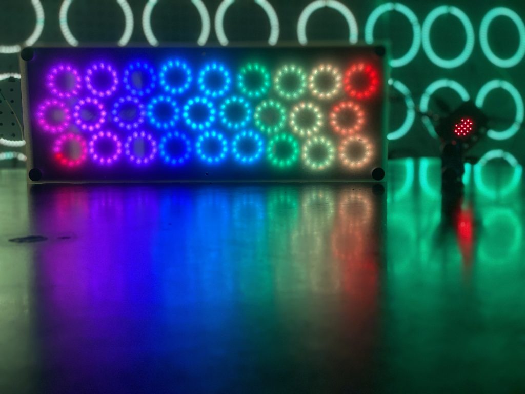
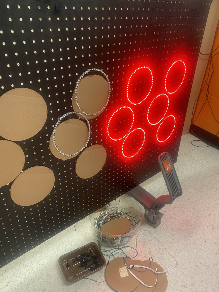
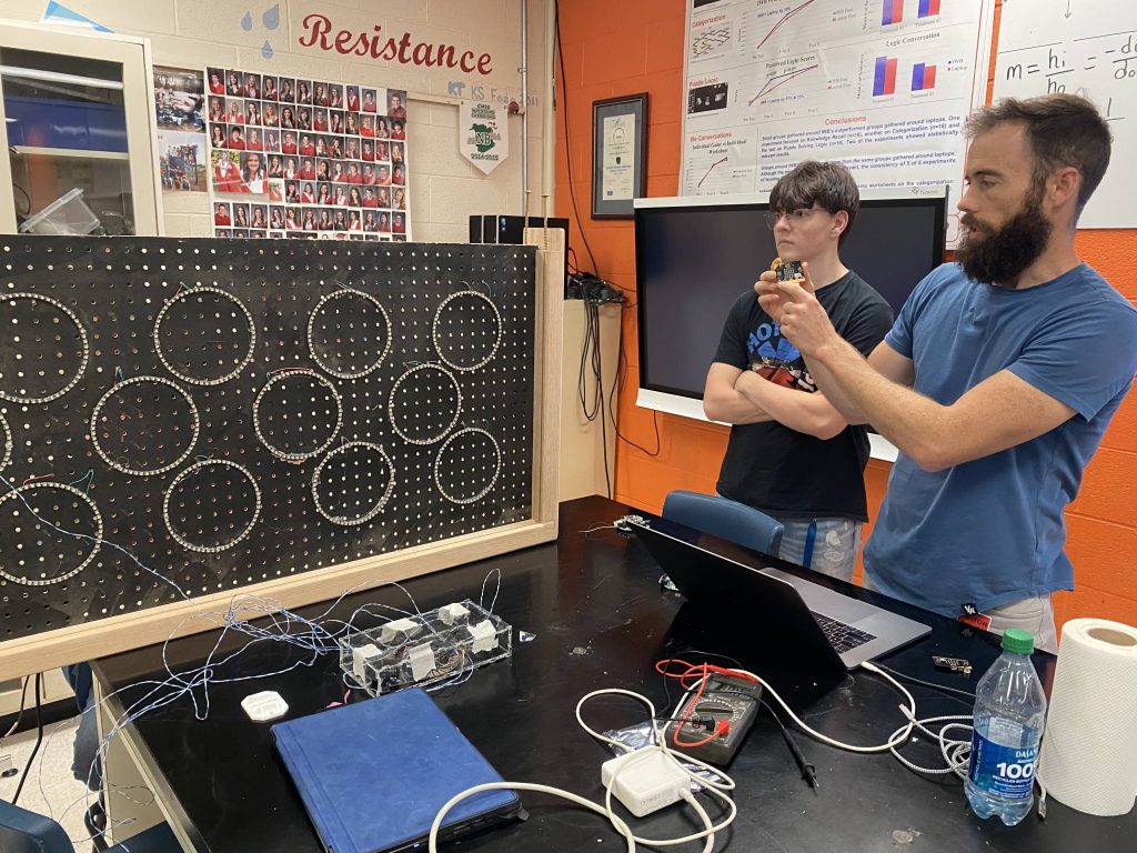
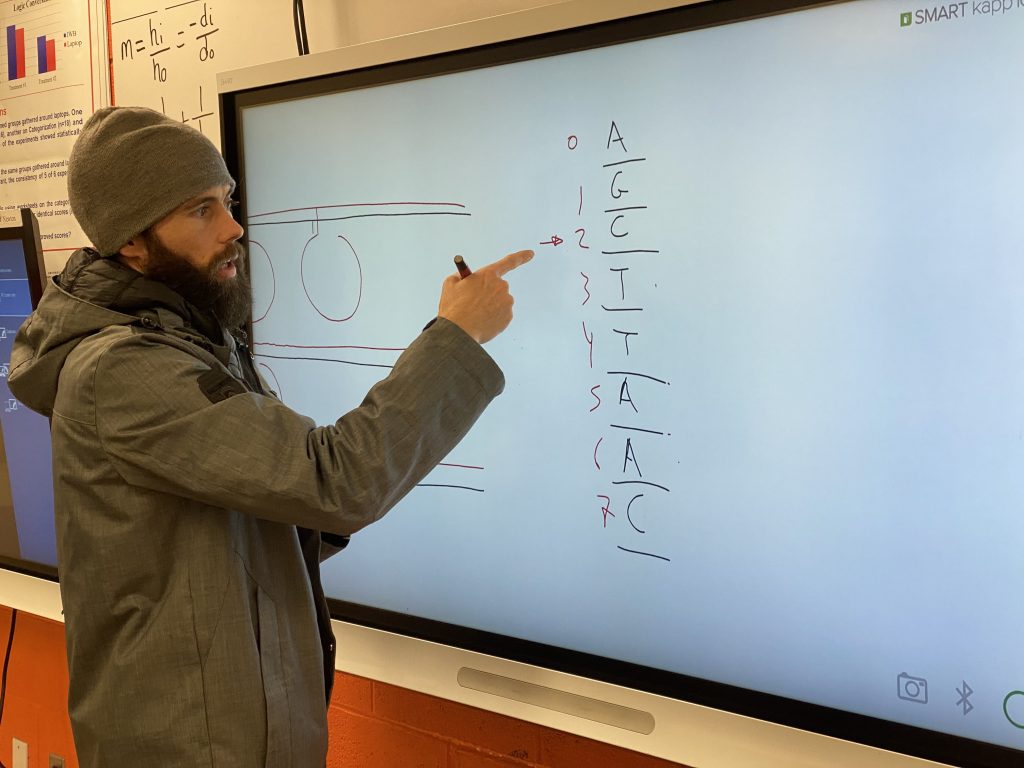
A 3×9 matrix of 6.2 inch LED rings from Adafruit will represent the DNA. The 3 ring rows represent the nucleic base pairs while the 9 columns represent 3 codons.
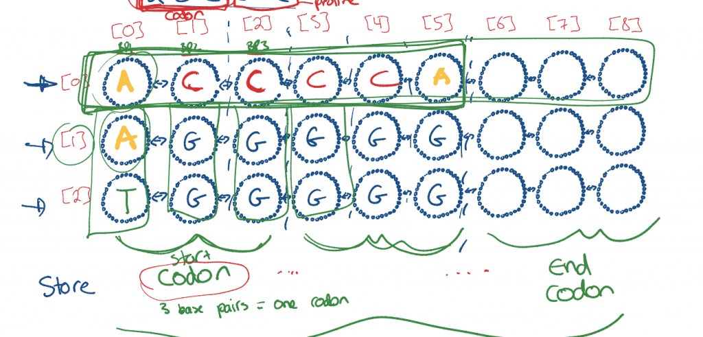
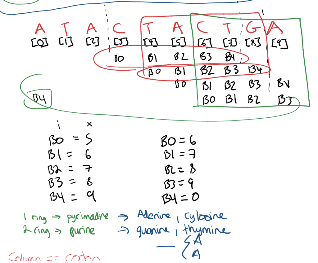
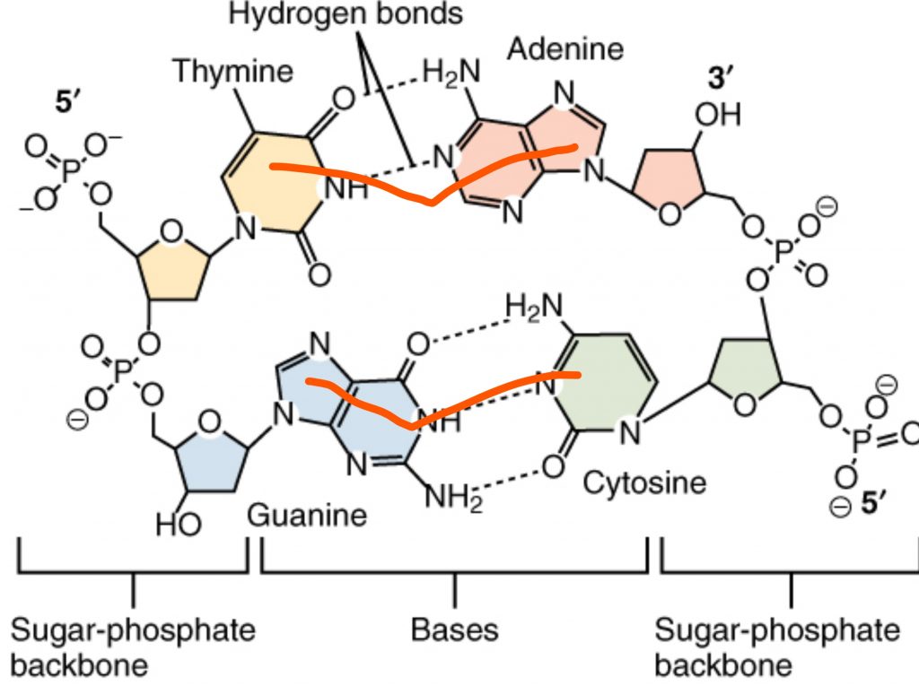
Nucleic Base Pairs: There are 5 flavours of nucleic acids, 4 of which combine together in DNA by hydrogen bonds to make Nucleic Base Pairs. Together, Adenine and Thymine have 3 rings total. Cytosine and Guanine also have 3 rings.
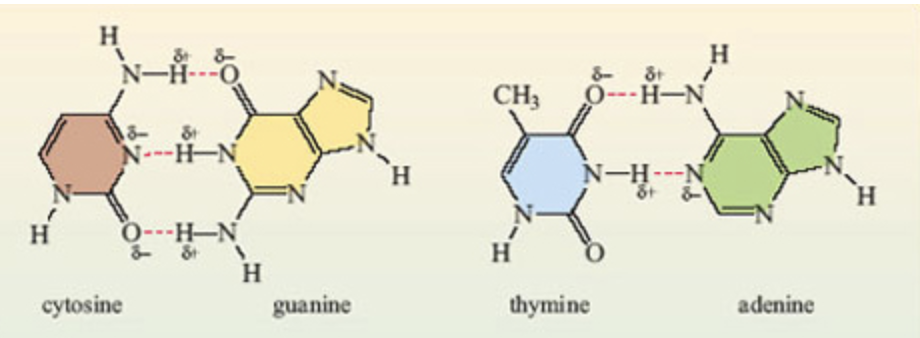
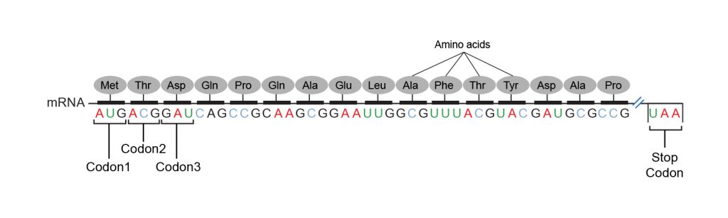
Codons: Three base pairs called codons combine together to give instructions during protein synthesis. Some codons tell the cells where to start and stop transcribing and which amino acids to place in what order in between.
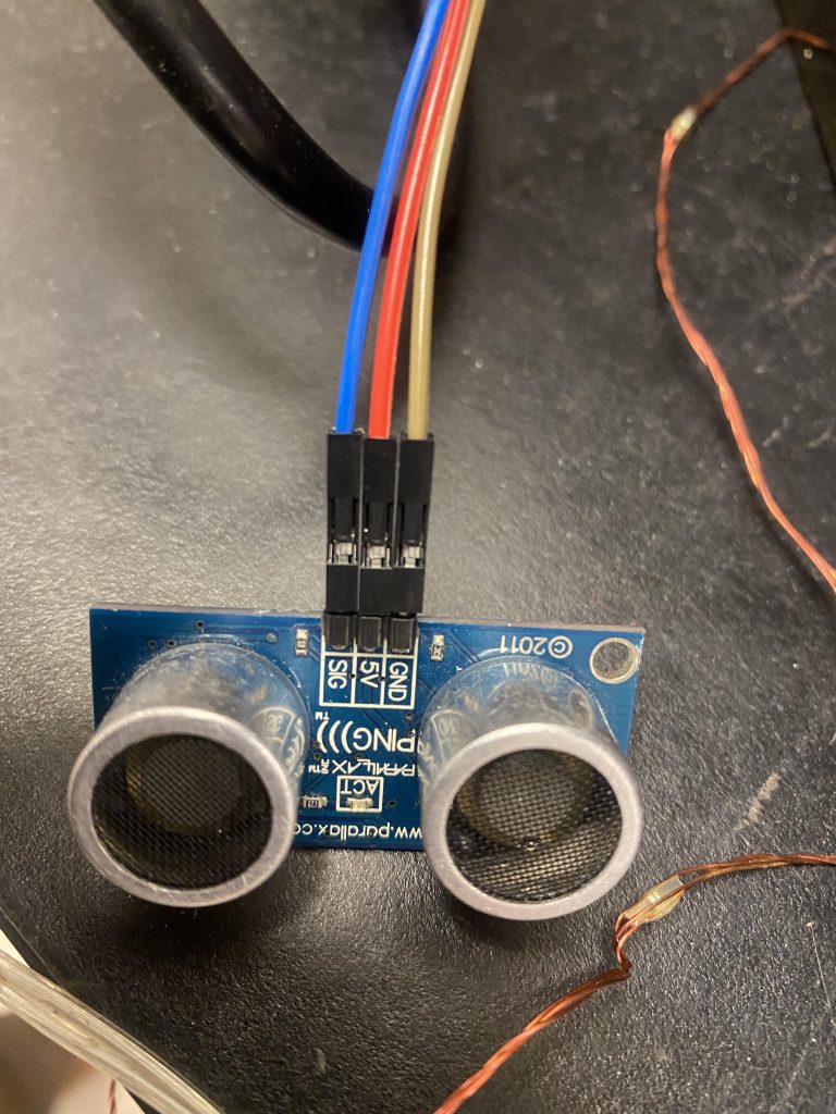
Human Interactivity: Our matrix can only display a small portion of a DNA sequence since even the smallest proteins would contains hundreds and thousands of codons. This is where the human interactivity comes in. What if a motion sensor could detect the motion of students walking down the hallway and transfer that motion to the light matrix. As students move left or right, the lights would also scroll left or right according to the DNA sequence. If the students move fast, it would scroll fast.Physics: The motion sensor acts as an echolocation device, sending out ultrasonic waves that bounce and return. They can use their physics 11 chapter on waves and kinematics to produce position-time and velocity-time graphs or calculations that would control the motion of the matrix.
Physics: The motion sensor acts as an echolocation device, sending out ultrasonic waves that bounce and return. They can use their physics 11 chapter on waves and kinematics to produce position time and velocity time graphs or calculations that would control the motion of the matrix.
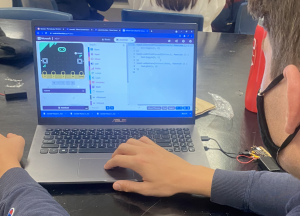
Coding with Microbits: The data needs to be interpreted by some kind of microcontroller. While there are many out there, the point is to have non-computer science people have a coding experience and yet be powerful enough to do what we need. Arduinos and RPis are certainly overkill for this application, but the learning curve for my non-comp sci kids is too large to keep them engaged. Remember, this is a physics project. The microbit seems ideal, because the block coding allows the novices to understand and participate in the computational thinking while also allowing the computer science kids to geek out on syntax and get double dip, getting physics and comp sci credit for the same work.
Let the fun begin! A Progress Blog
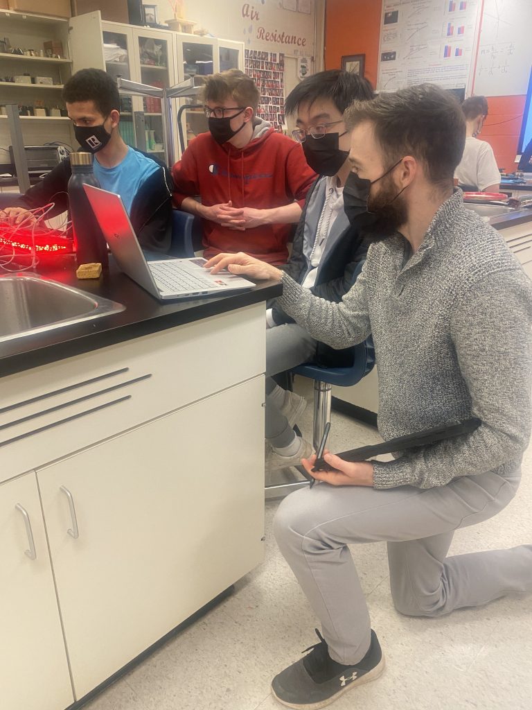
Josh and Jacob at Brilliant Labs were quick to jump on board to provide both the technical and the financial support for this project. It is way outside the scope of our school budget and I have nowhere near the coding experience to effectively mentor the students. If we are going to have creativity, students need to discuss, debate and argue about strategy, plans of attack, etc… There is a fine line between taking physics that requires a little bit of learning in biology and coding and abandoning the physics content because there is so much scaffold learning to happen. This is where Josh works so well. He is an electrical engineer with Brilliant Labs, but he inherited the spirit of an educator from one of his previous lives. We figured out that this is a reasonable microbit project for students and Brilliant Labs had the resources to cover the initial finances.
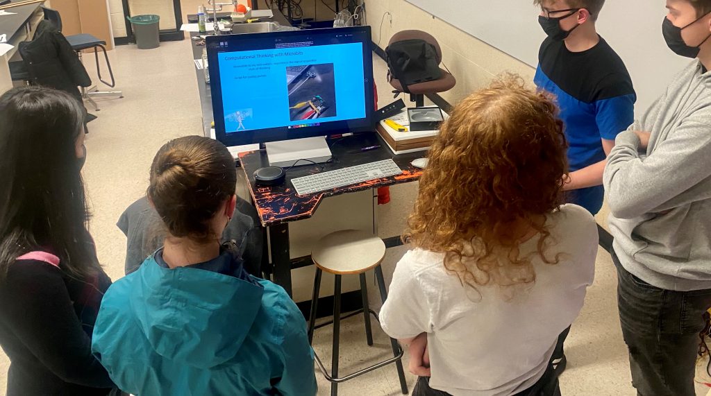
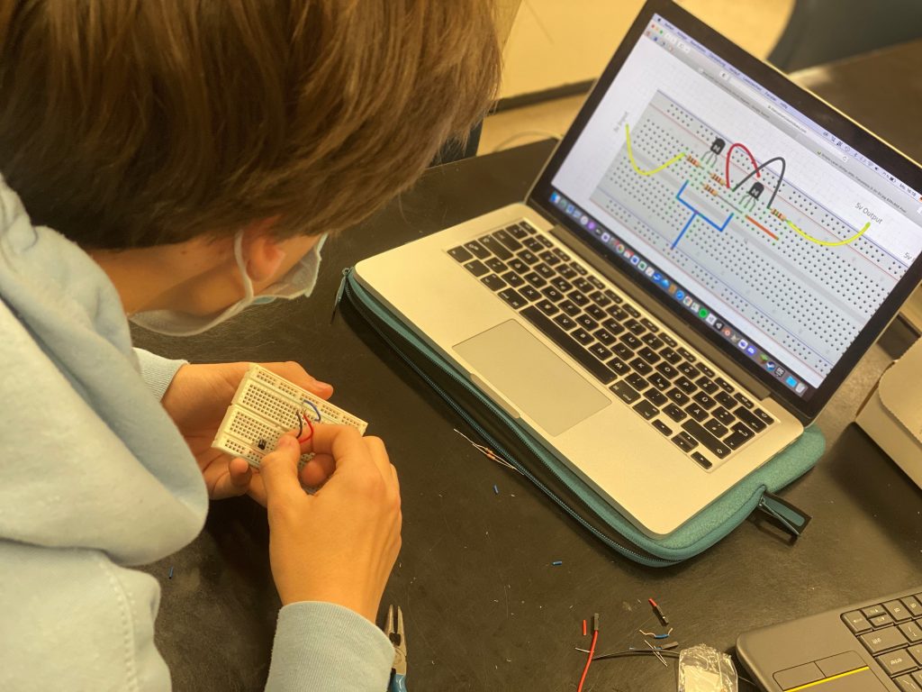
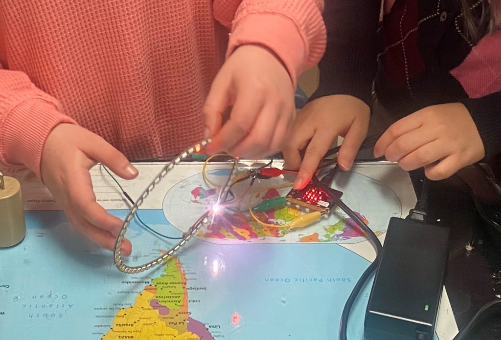
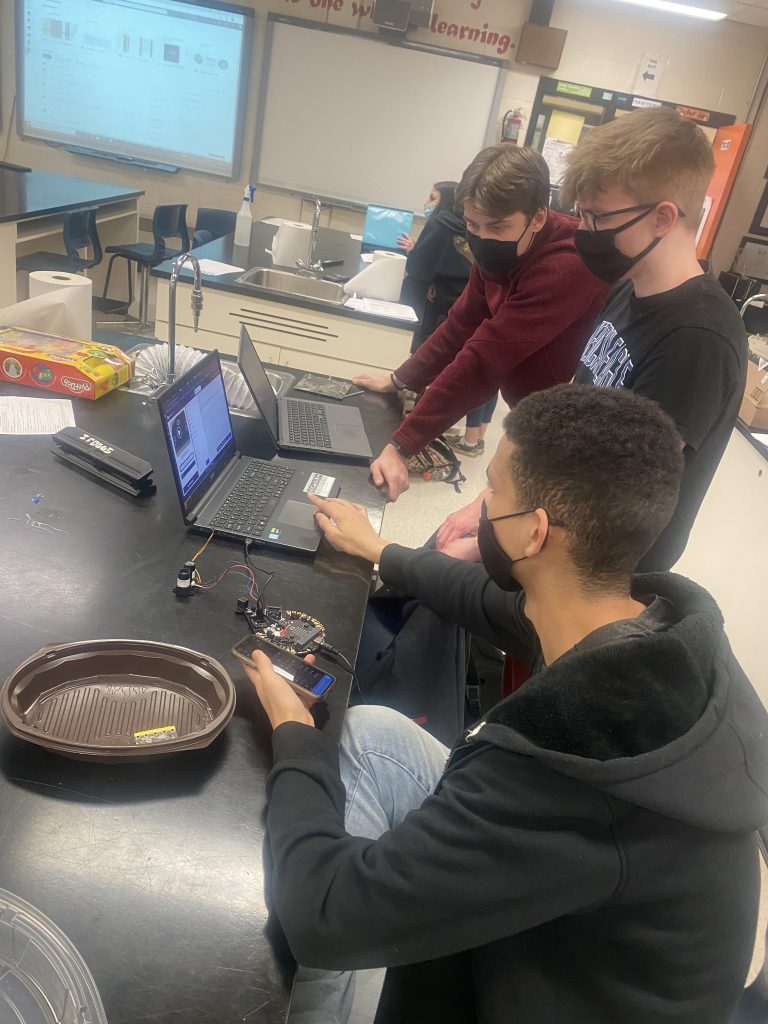
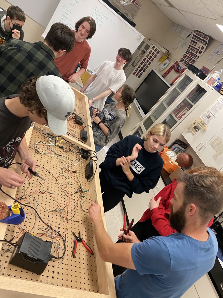
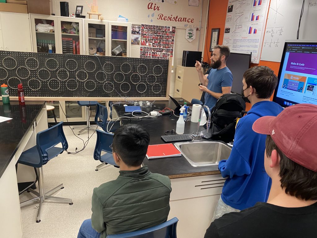
Lunch Time DNArt meetings: Meeting #1. We started meeting Mondays at lunches to begin our projects. This allowed students from P3 and P4 to co-mingle in the same room and act as a team. Meeting #1 was a quick overview of what we wanted to accomplish and the idea of trans-disciplinary learning. It is OK to have a favourite area, and a preferred task, but it is important that everyone has an experience in every field.
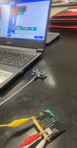
Meeting #2: Intro to Microbit: How do you plug in a microbit? How block coding works. How to display on the microbit screen when buttons are pressed.
Meeting #2: Intro to Microbit: How do you plug in a microbit? How block coding works. How to display on the microbit screen when buttons are pressed.
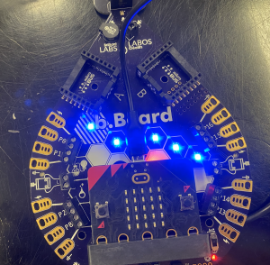
Meeting #3: Intro to bBoard: How to use the Blixels and play music based on pressing buttons.
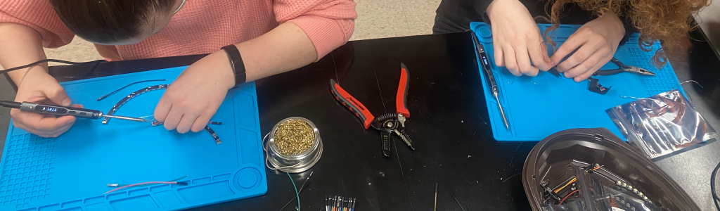
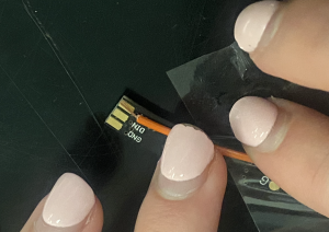
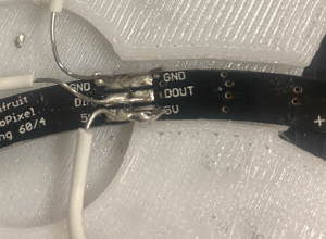
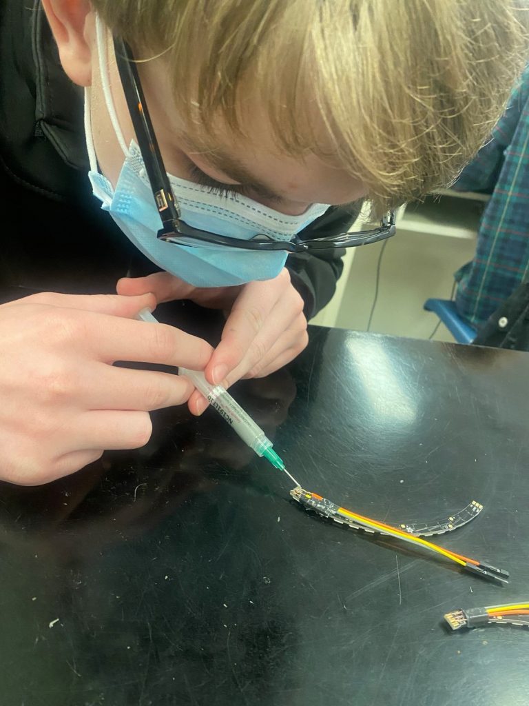
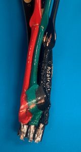
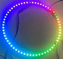
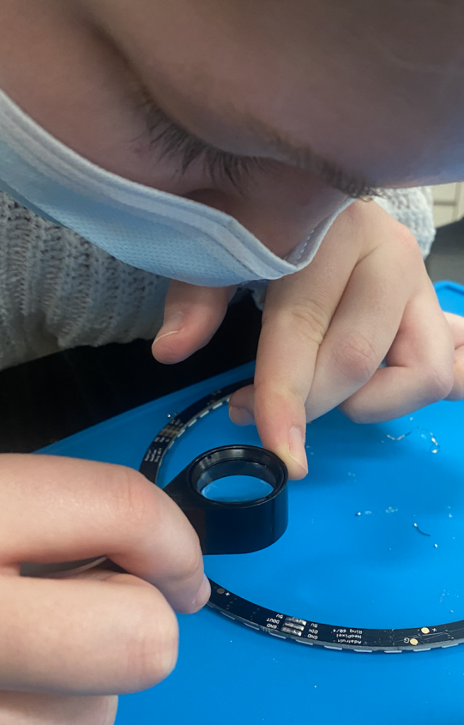
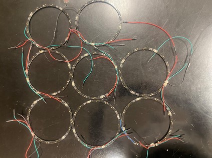
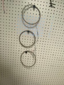
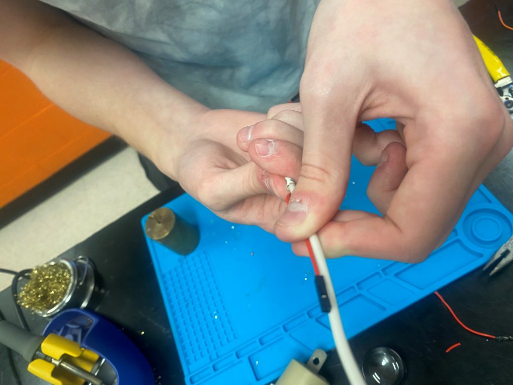
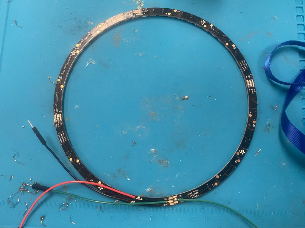
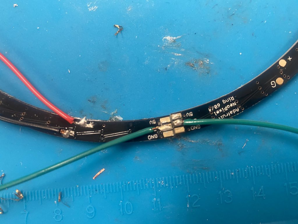
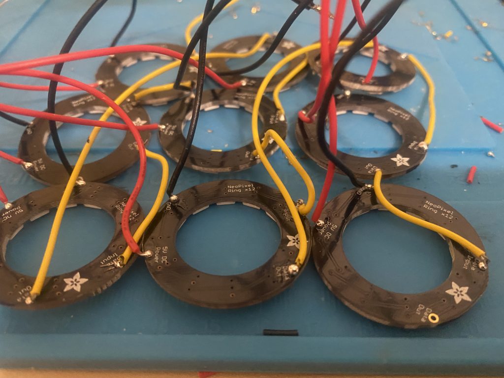
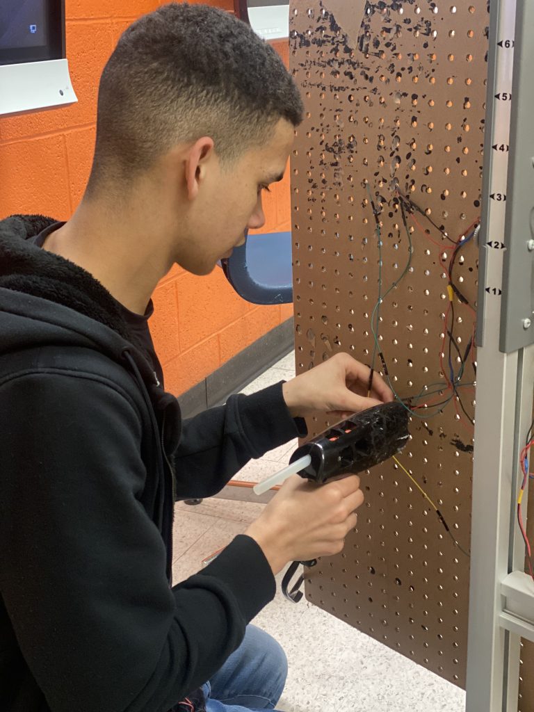
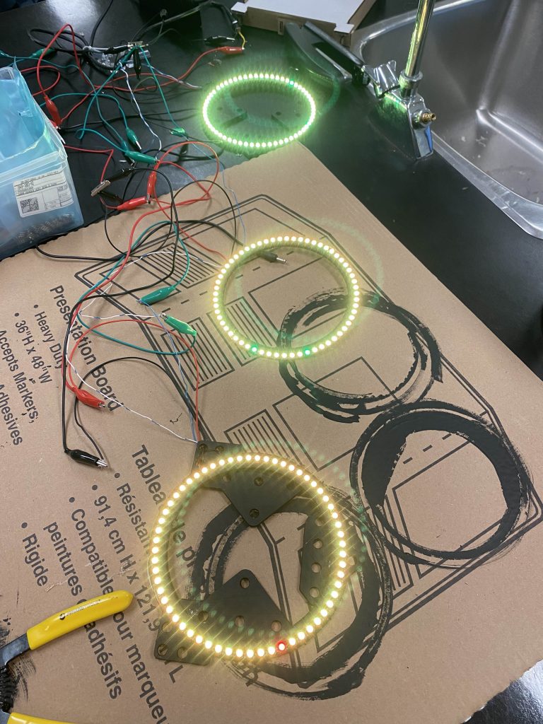
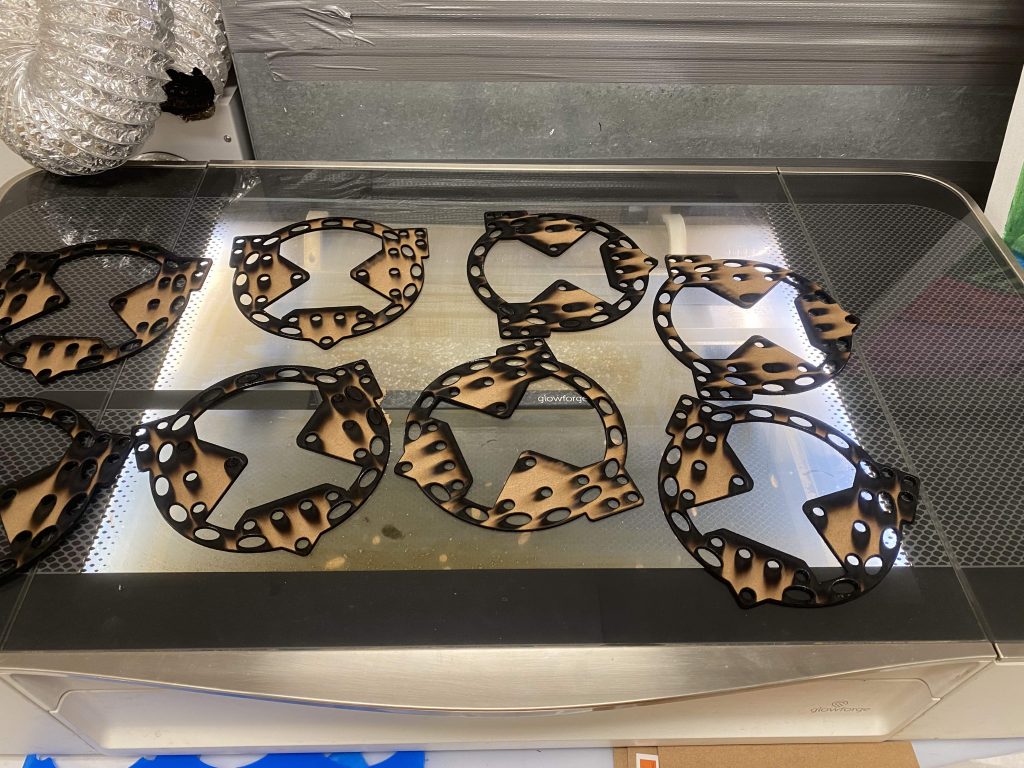
Meeting #4: Adafruit 60 LED ring segments and 5V-10 A power supplies arrived. Time to teach how to solder. We first showed how to add wires to the 5V, GND and Data pads. Some students have soldered before, but many have not. We are asking them to run before they can walk. About half the rings that they made did not work. They are struggling to prevent short circuits. Also, the solder connections at the joints are precarious.
Meeting #5: Can we use solder paste to help prevent short circuits? Can we use a small piece of wire to help support the solder bridges between segments? Using the heat gun with the solder paste blew the wires all over the place, even using tape or clamps. Perhaps this is not a solution. We put out an all call for a toaster oven from the staff. We could use this in our LEO project as well. No one volunteered an old toaster oven. So we will need to look at buying one. We have no money at the moment, and I am reluctant to ask Brilliant Labs. They have already been very generous and we need to have some more skin in the game. I’ll apply for a Sustainapalooza grant.
Meeting #6a. Writing the grant. I assigned the grant writing process to a student (M) who very much struggles with sentences and spelling. This is a large task, which she attacks over 3 lunch hours and a couple of after schools. After her experience with LEO last year, she is excited and engaged in the process, even though I am asking her to work in an area of discomfort. Once the first draft was done (about 1.5 weeks), I helped her evolve to 5 more drafts. They were finally submitted and fast forward….accepted. We will have money for this eventually,… but not yet. We will have to continue using solder bridges while we wait.
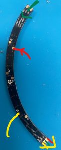
Meeting #6b: Perhaps we can use the 5V and GND pads in the middle of the segments so that there is lots of gaps between the wires. We have almost eliminated the short circuiting issues.
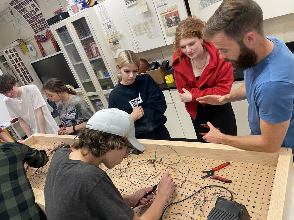
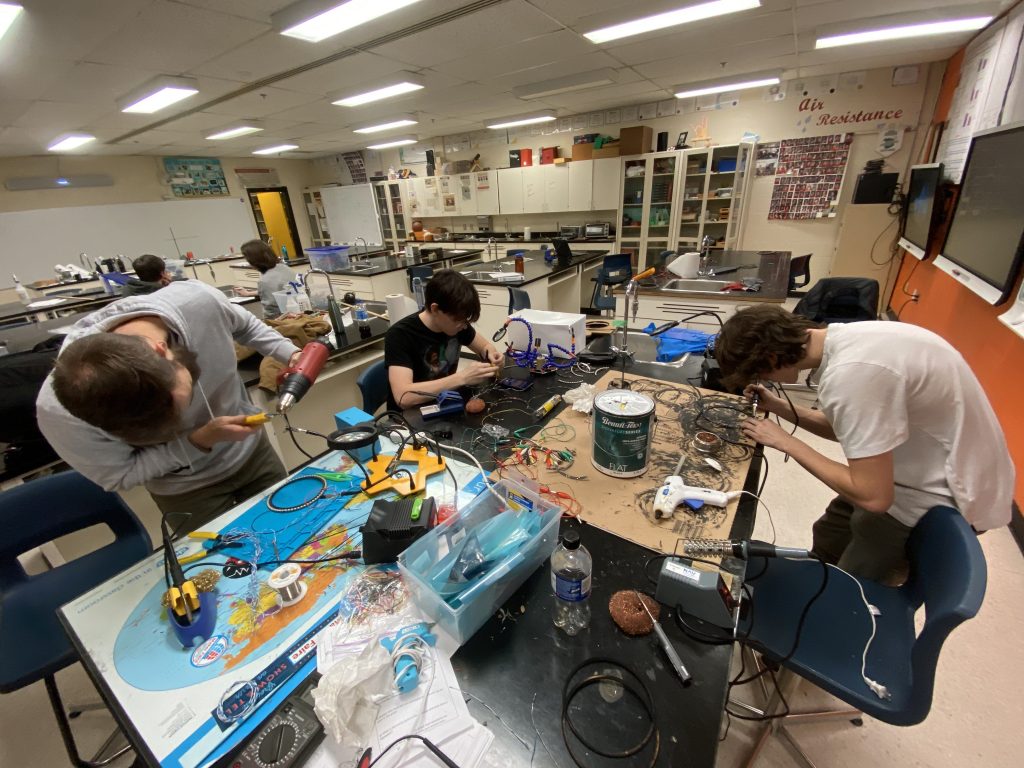
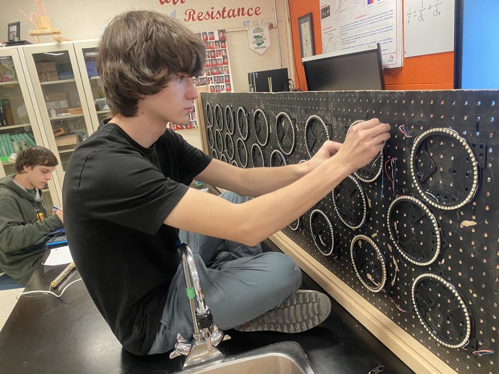
Now students are logging additional hours outside our scheduled weekly lunch meeting, soldering and assembling rings as they have a few moments here and there. The project is starting to occupy my back desk and getting attention of other students in my physics classes and also in my math classes. Students are teaching other students how to solder.
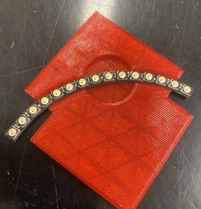
3D printed Jig: Trying to hold the segments, maintain level and circular was a challenge. What if we made a 3D printed Jig? Two small groups of students learned how to 3D print using Tinker Cad and 3D builder. We printed a couple of jigs that would hold the segments. They were not quite sized correctly. Using PLA they were either too big or too small. The segments also do not form a perfect circle. What if we printed in flexible filament so that the segments would snap into place a little bit. After 2 weeks and 5 iterations, we have something that Works like a charm!!
Meeting #7. We tried using crazy glue to help secure the light segments. We layered some saran wrap between the 3D printed jig and the segments. This process worked nicely, but only after school so that students were not breathing in fumes all day long. However, as students trouble shoot other students’ work, there are fumes that are released when the soldering iron comes close to the dried glue. Perhaps we can use hot glue to not only secure the segments, but also prevent short circuits in the wires and secure the wires to the segments, reducing the stress on the solder joints.
Meeting #8. GREAT NEWS: MICROBIT LIVE! After a tweet about our work, Martha from Fairchance Learning suggested that we apply to present at the BBC Microbit Live global event. So again, I put a student on the writing process, we submitted and…we were accepted. We have the first slot after the keynote on Day 1! Prime time! for 5 minutes the world’s top educators using microbits will be listening to us!! we have some serious work to do to get ready.

ROAD BLOCK: We are only 4 weeks away from the Microbit Live presentation, and now schools are closed because of a labor strike by the custodians, office admin and bus drivers. Two weeks gone!
Meeting #9 The Blitz: School is back. We need a blitz. Josh planned to come from Fredericton to Moncton for the day. I re-arranged my whole week to so that supply teachers could administer tests and minimize the disruption. Of course, it is an exercise in patience. There is a huge rain/freezing rain/ flurries storm on the day Josh was to come. It is a good thing we are getting better at the virtual thing.
C’s Code: “C” had been thinking about the code for this project for a month now and was finally ready to start talking, problem solving, creating etc… So C and Josh spent the afternoon together geeking out over Code, and test driving different layers with the 5 rings that were functional.
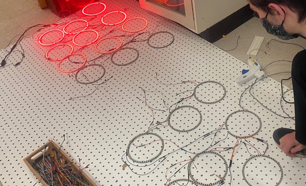
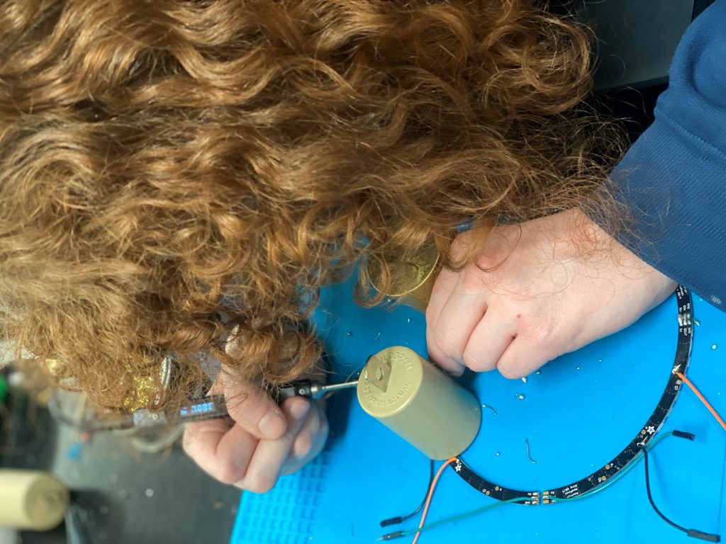
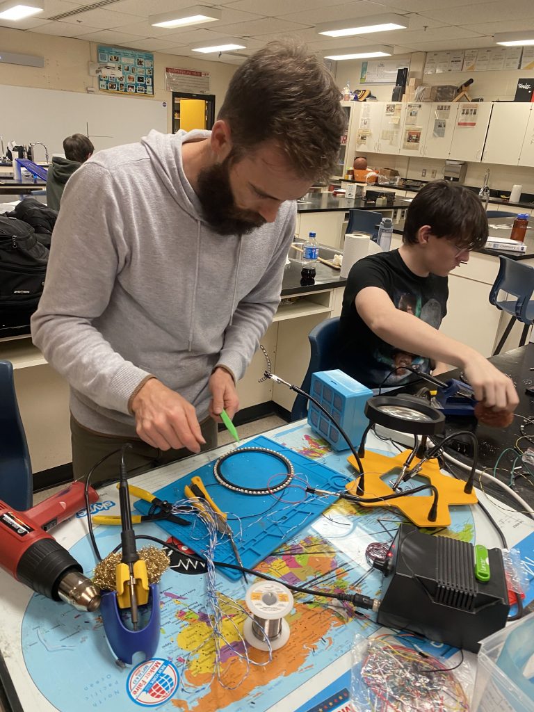
Meanwhile, I took the DNArt students and students who had not yet started their projects to the innovation hub where we soldered. Kids who had never soldered found it fun. D talked about how they really loved the fine hands on detail of building solder bridges. They want to be a doctor, perhaps surgery is in their future? Again, watching students teach other students was warming to the heart of an educator. They were having so much fun, but were not finished, that 12 of them went to their period 5 teachers (last period of the day) and asked to continue their work in physics class. We tripled the number of rings made. Some will need trouble shooting.
L’s Rings: “L” had been falling asleep in physics class for the first 2 months and now that report cards are out, they realized that they had to start working. They had done a bit of soldering on the blitz day and seemed to really like it. They started coming in at lunches and even an after school to start troubleshooting other students’ rings. They typically struggled for 1.5 hours to fix one ring. It took time to figure out what the problem was and then to fix it. Just when they thought they were done, a new problem was discovered. But, this was followed by elation the first time they got someone else’s broken ring to work. They were hooked! They fixed 3 more rings over three more lunches and after schools. They owed me a remake for chapter 2 test. I postponed the remake so that I did not interrupt the flow. They spent the next weekend preparing for the very delayed physics test and scored 10 points higher than the previous unit.
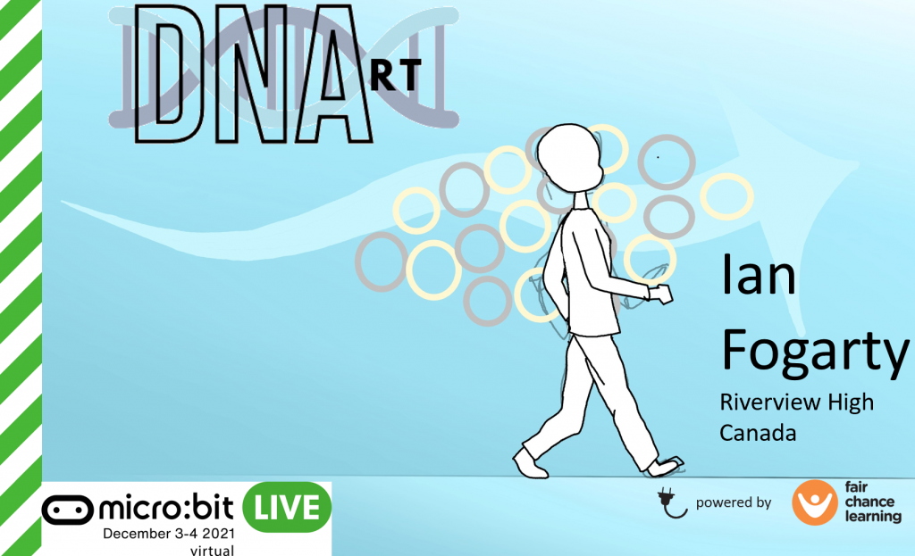
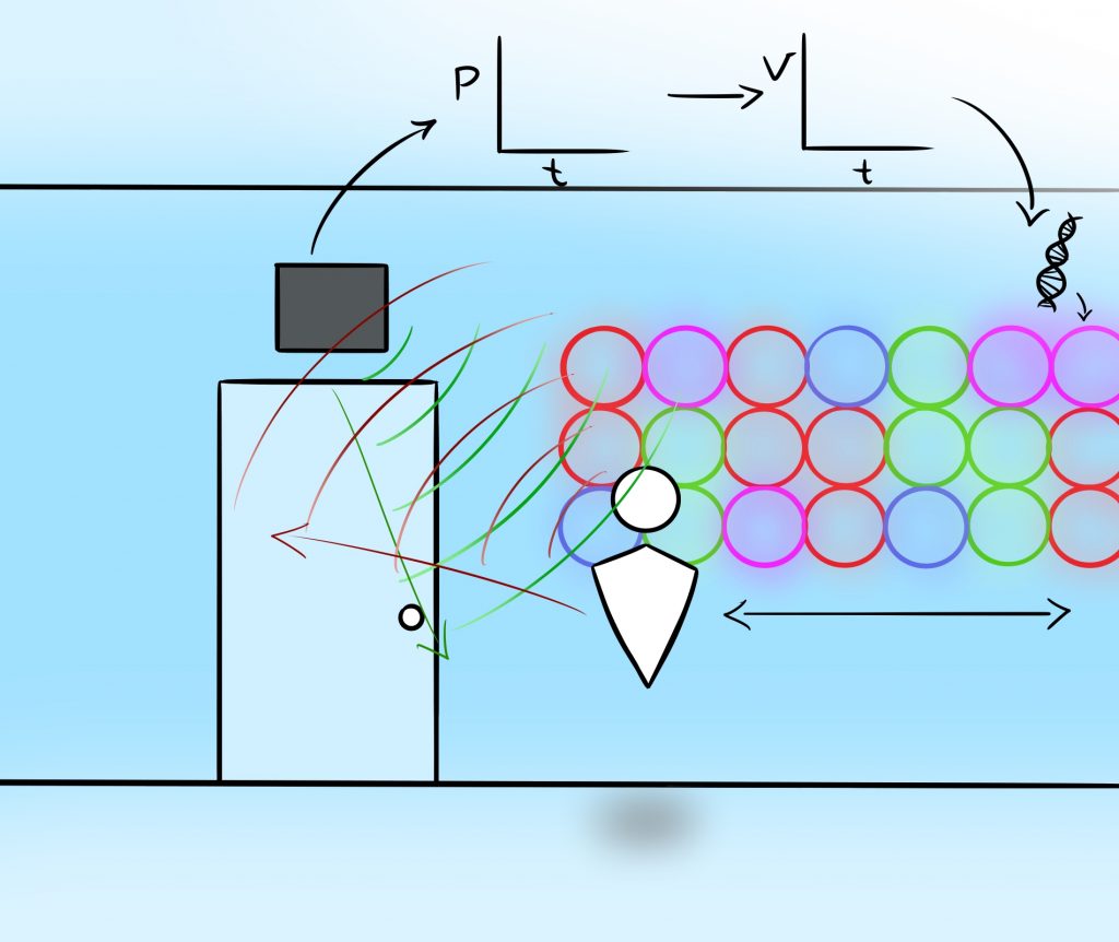
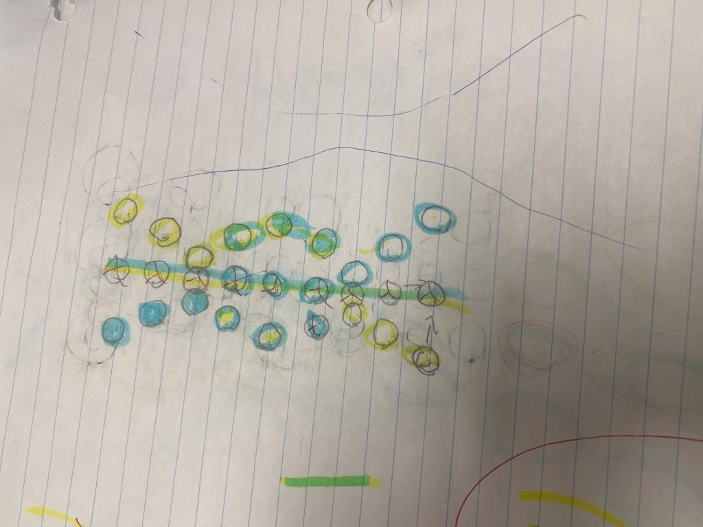
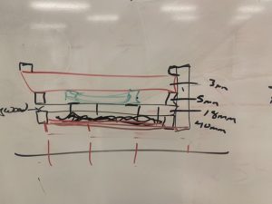
R’s Logo: One of my struggling math students (R) spends a bunch of time decorating his mostly blank math tests with intricate designs. I wondered about their future path. They were planning to do art professionally. It turns out that they like to build art in the shop and prefer to doodle digitally. After a conversation with parents and consultation with resource and school team, it was decided that they would drop the optional math and focus on other things. In an attempt to engage them, I described our project and asked if they would create some kind of graphic for us. Within 30 min, they delivered the blue graphic at the top of the page.
R’s Logo: One of my struggling math students (R) spends a bunch of time decorating his mostly blank math tests with intricate designs. I wondered their future path. They were planning to do art professionally. It turns out that they like to build art in the shop and prefers to doodle digitally. After a conversation with parents and consultation with resource and school team, it was decided that they would drop the optional math and focus on other things. In an attempt to engage them, I described our project and asked if they would create some kind of graphic for us. Within 30 min, they delivered the blue graphic at the top of the page.
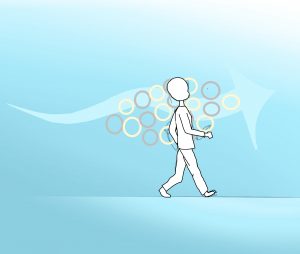
I like how the sketching part not only shows the movement of the person interacting with the art, but also tries to make the “layers visible” (art educator lingo) so that the iterations and process are communicated. This is a process from art that I hope my future scientists adopt.
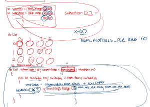
K’s Code: K has some experience with coding and I had originally wondered if they would take on the sensor portion of the code. However, on Blitz day, they chose to stay with the soldering, which I assured them was fine. The next day, in an unrelated rant to both my physics classes, I talked about how lots of people would have great grades, but projects like DNArt are not common place. I talked about the idea of doing things, not because of a grade, but because of their own value and how that would in turn lead to unpredictable opportunities. My son Fin is a great example of this. Apparently that night, K had a terrible bout of insomnia, and a possible coding path was inspired. They got out of bed, spent some time in the wee hours of the morning coding. The next day, they came in all excited to show me the work. It WORKED!!! They confided in me that they did not want the responsibility of doing that code on their shoulders and had no intention of doing the code, but my speech had caused them to reconsider, insomnia happened, code was created, conflict changed to success, sleep happened. Now K and C are working on opposite sides of the code, similar to building a bridge from both ends. They just need to agree on what the middle looks like so that when they hand the baton from one code to another, it all works. (Sorry for changing my metaphors here).
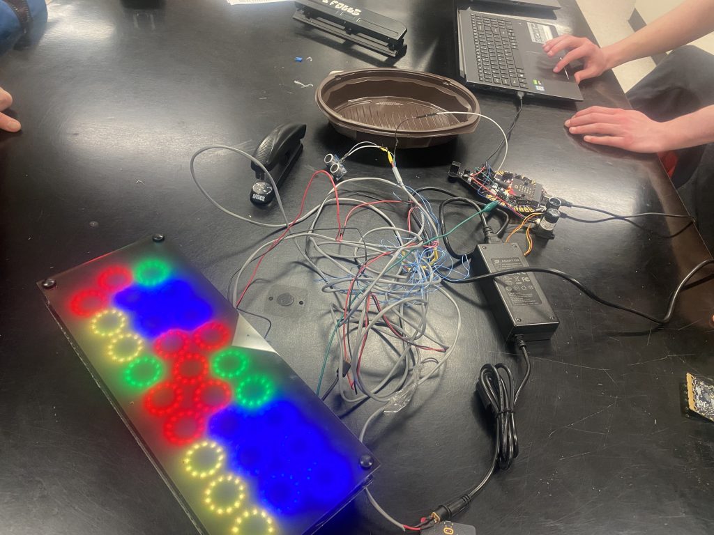
The Mysterious 6th ring- Start at the Start: As we add rings to our chain in series, the 6th ring seems to be trouble. Why? After 2 hours of checking short circuits, swapping rings in and out, is the problem in receiving the data? perhaps the previous ring was not sending data? Was there a loose connection that was working sometimes and not others? We know we had to worry about having enough power at the end of the string. Each ring has 60 LEDs and we have 6 rings. Perhaps the power supply is a problem? Here is the video that I sent to Josh. It was only after I created the video that I wondered about C’s code. Perhaps they had limited it to 5 rings? Coincidentally, I was on morning bus duty the next day when C walked by. He confirmed that the code was only meant for 5 rings!! This is a great example of wasted time because of simple assumptions and not starting at the start.
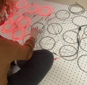
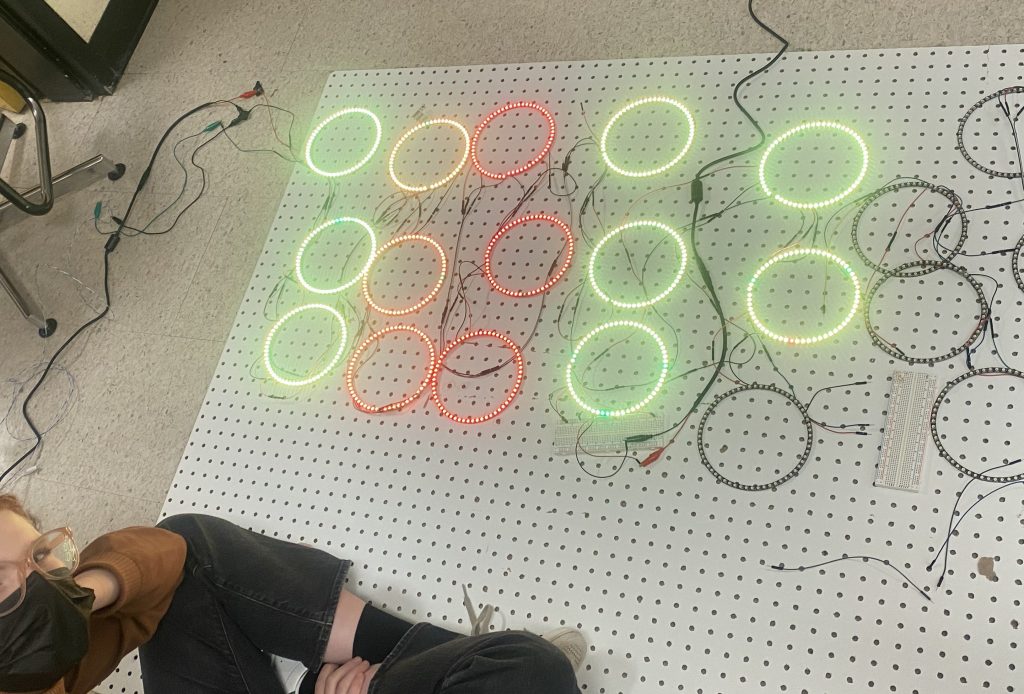
Puzzle Solving Rings: How do these rings go together in a larger sequence? When a ring does not work, is it a soldering issue? Is it an issue with the ring at hand, or perhaps the previous ring is not sending the data? A lunch and an afterschool and we seem to have about 12 rings working, but there are power issues. We are close to our Microbit Live event, so let’s back off to 9 rings. We will need to sort out the power issue later.
Microbit Live Event: On Dec 3rd, 2021, we are invited to give a 5 min Lightning talk immediately following the Opening Keynote. This is the most coveted position and it is ours. We need to get ready. We do not have many rings assembled, the code does not work yet, and we need some graphics.
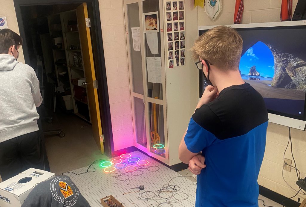
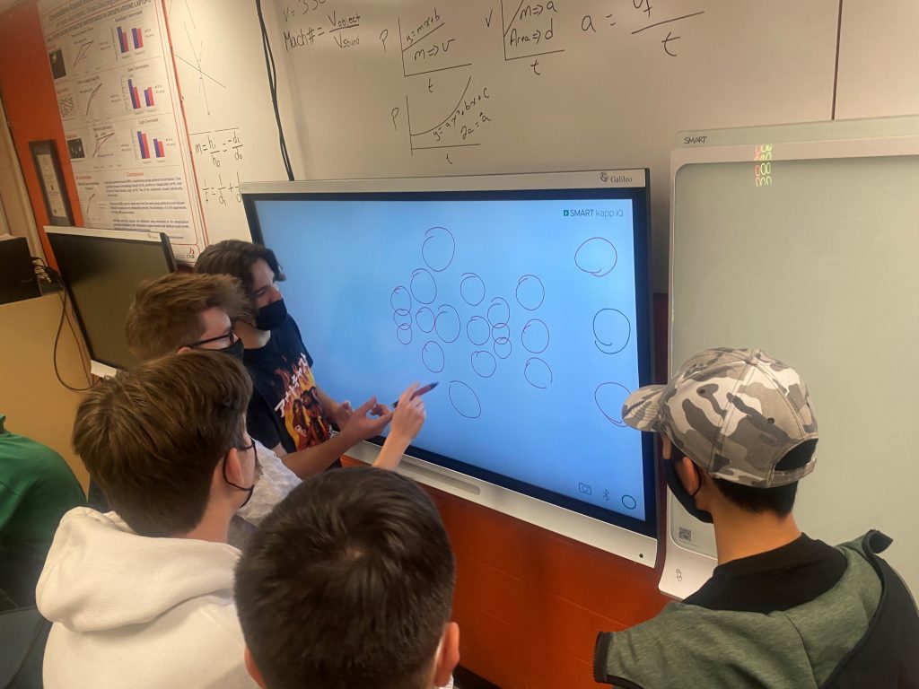
The pressure is mounting. At lunch time, not only were C and K gathered around tying to figure out how it worked, but there was also 5 other students who were gathered around adding their 2 cents worth. When the lights were not turned on, the general student population just walked by it. When the lights were just on, students walked by it but looked at it. Once the lights were moving AND there were students who were speaking loudly about the process and the puzzle, all of sudden there was a crowd talking about possible code issues. The emotion in the room was contagious. The bell to end lunch and start my physics class rang. Two students would sit and do the word problem, then immediately try to problem solve the code, did the physics word problem when they needed to and then work on the code. By the end of the day, the code did not work. More on this later.
D’d design: Since we won’t be done our work in time for the Microbit Event, we needed a graphic to describe what was going on. “D” took it on. At first, they gave me something with beige, but after seeing “R’s walking person, changed the colour scheme- this is a critical piece!
Saying “yes”: Students knew that presenting to an outside audience gave them 2 extra points of their project, and so were a little disappointed that they could not be part of the presentation. I was able to get special permission for students to attend school (it is a day off for the students) for the presentation as well as the evening before for the dress rehearsal. I informed the class, but with such short notice, no one could go because of work, or sports etc.. One exchange student, S, who is learning English jumped forward enthusiastically to come to the meeting later that evening to practice. She would be the only one. After talking out loud, another student R, decided to join so that S would not be alone. Now that R was going, maybe E would join despite being so nervous that she typically is sick to her stomach. They could not come until 6 pm. Well, since the code is not done, maybe C and K could hang out after school and work. Since they are going to be after school anyway, they might as well do the dress rehearsal with everyone else. They decided they might as well speak too. Another lesson in how one person or two can make a difference, how taking a step as a single person can build and the importance of a first follower. If R had not been the first follower, perhaps S would have backed down.
So from 4:30 pm-8: pm, we had lots of good conversations with lots of puzzle solving, and creativity. K & C had spent days trying to figure out the code often saying, “We take two steps forward and one step back”. Finally around 5:30 ( 36.5 hours from presentation time)- VICTORY! Insert video? They returned home for a quick bite to eat and then returned to class with everyone else at 6 pm. Some came straight from skating and others from work. All of them made significant sacrifices to be there.
Dress Rehearsal: I had already spent some time making a script because originally, this was going to be my talk. The students made some suggestions around formatting, changed the video and added some slides. Now it’s time to practice. It is odd talking out loud to an invisible audience beside peers. One struggles with some of the words, another is too quiet, other struggles on what to say and I am too fast for the international audience. Some more student changes to the order, the content and the slide composition, a few more run throughs and we are at 4:50 sec of our 5 min presentation!! We are Ready!!
E’s design: Weeks ago, E took it on to create a logo. I only got to see them today. Wonderfully, she created something that looked like a logo, where R created a cool graphic and D created a flow diagram. Three pieces of a puzzle. Just by chance, two of them had similar blue and light grey colour schemes.


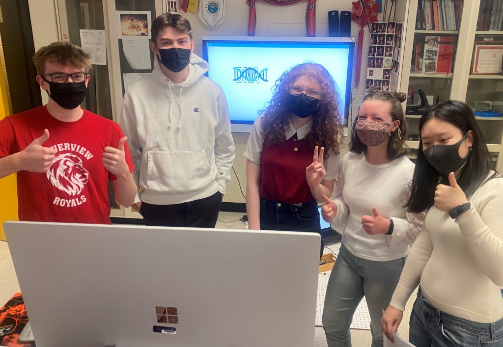
Game Day: Dec 3rd. The next morning, the Keynote is in progress. I cannot seem to test our mic and speakers. Students arrive ahead of time wearing red and white and looking great. After all the work last night, C had gone home and built a program that would make the logo move around the screen. That was up and running.
There are now 92 countries represented and over the next 32 hours, there will be some 80 presentations. We get the coveted spot. There are only 10 min before go time and we still are unable to control our screen or share our voice. We are in the right virtual spot. 5 min before go time and we finally control, but the process asks us to check our speakers and cameras and mics.
We have a problem with our camera and mic. It is go time and we can only type. They ask us to log out and log back in. Just as I am abut to click to log out, we gain mic privileges’. It appears as though they had issues promoting us to speakers.
It freaked the kids out a bit. But its a go!
The screen share happens, The talk happens and…the students perform wonderfully. No stammering, no pauses, good volume, good pace! Well done! This is another victory for all of them and at a time when they could have been home in bed! When it was over, I had to go to some PL sessions, they stayed behind to talk about the next steps in the project. This is going to be the start of public speaking careers for some. It has happened before in other projects and I expect it will happen again with this.
Having the courage to overcome is empowering. Having an event with a deadline and a global stage on which to perform is a key ingredient to motivation, time management, triage, and self-confidence. NB can compete with the rest of the world. Cool things happen right here at home, if you make them happen.
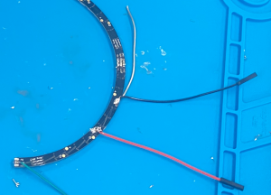
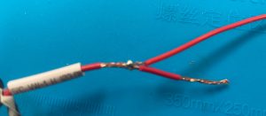
“Captain, We Need MORE POWER”: We are seeing that some of the rings in series are getting more and more dim near the ends. We see that when high intensity colours are signaled, like bright yellow, rings that are further down the line show orange or even red. We are using only one power supply in a series circuit with fine gauged jumper wires. This means all of the current needs to flow through one jumper wire. When I added a second power supply in the middle of the string, I had to have a 3 way connection. We used a breadboard. It did not take long for the breadboard to get hot. This is not good. We need a new solution.
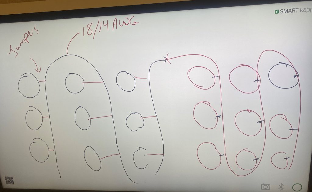
The data would need to be in a series circuit, but the power could be in parallel. One student tried a crude way of just connecting all the 5V jumper wires together in one bundle and trying to twist them together. Not only was it unwieldly, it was difficult to keep all the wires connected and it also meant that some of the further rings would need multiple jumper wires to make the distance.
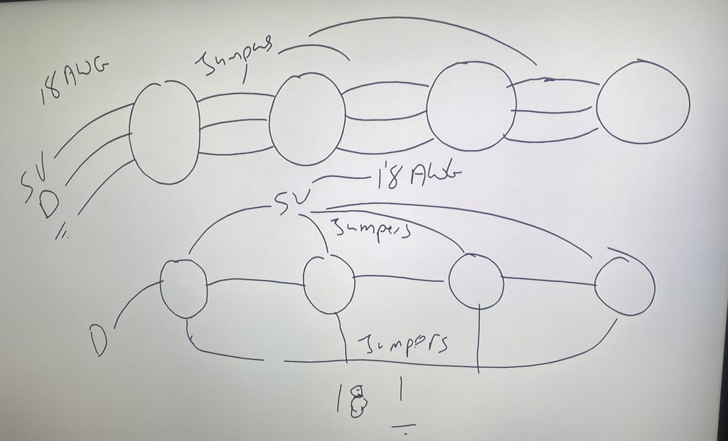
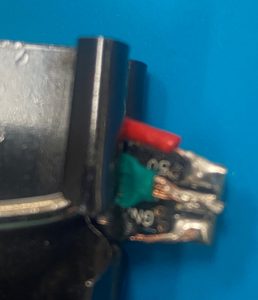
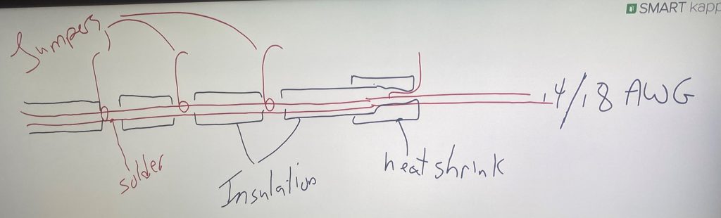
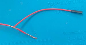
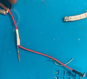
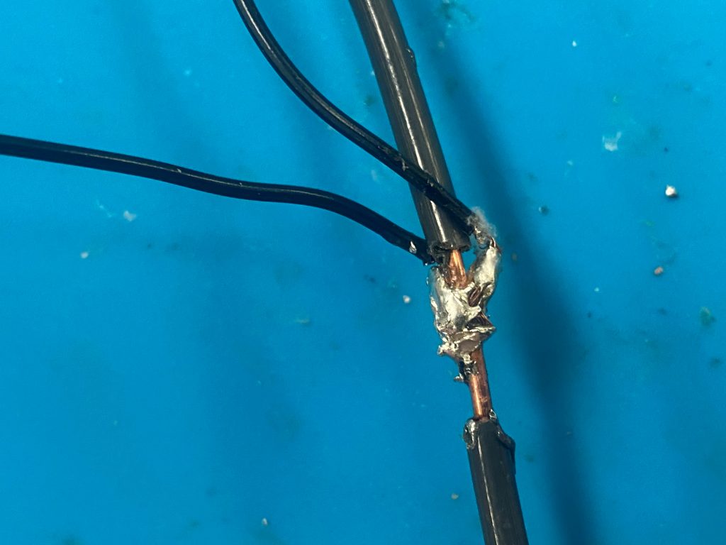
We came up with the idea of making a manifold. Could we use large gauge wire, strip small sections of insulation off, steal one of the jumpers from the ring, and solder it to the heavy gauge. Cover it in heat shrink. Dedicate one codon to one power supply and then connect the ends of the power supplies together. for redundancy. Now that the Microbit Live session is over, we can regroup and pace ourselves. Now that there is more interest, we can get people to do some of the grunt work.
“I love to SOLDER! I did not think I would, but I do!”
Resistance of Wire and Gauge: After the Microbit presentation, we noticed some heat in the breadboard. This is not the first time we noticed some heat. Some students started making manifold wires using the 18 gauge speaker wire from LEO. Josh thought we should go to 14 gauge solid core. I did not have any 14 gauge, and students are starting to volunteer to work on this project now that time is getting close and they do not have any project marks yet. I found some 14 gauge solid core house wire in the shop. Let’s do as little experiment. Is there a noticeable difference in the voltage drop between the gauges. We are going to be using about 10 ft. Just hooking up a length of wire to our power supply and no load, we did not observe any difference between the 24, 18 and 14 gauge wires. This must be because of the lack of load. Something to try once we have a series of rings on it.
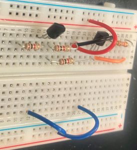
Voltage Shifter: Josh is worried that the 3.3V data signal coming out of the microbit may be causing problems with the 5V from the power supply and the rings. He suggested we make a voltage shifter with some NPN transistors. This sounds like a job for “R”, one of my exchange students. He says he has never done anything with electronics before, but despite the language issues, they are really insightful and intuitive. I gave hi ma breadboard and a few things, a link to a web page and off he went. Within 30 min, there was a shifter. We are not sure how to test it. the output seems to be 5 V, but since it is connected to a 5V power supply, that may not be significant. How do we know our signal is getting boosted to 5V and we are not just measuring the power supply?
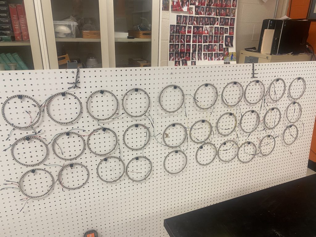
Peg Board: There were a few near misses with the rings being on the floor. It was great for the Microbit presentation, but not so good with many classes coming and going. Maybe we need to have the pegboard vertical on wheels so we can easily access , move it out of the way and access the back for the wiring. I acquired a Smartboard on wheels. Students replaced the Smartboard with Pegboard. But how are we going to hand the rings? We need pegs. It is true that we could go buy some (students did not know that), but then we would miss an opportunity to solve a problem by learning something, in this case 3D printing.
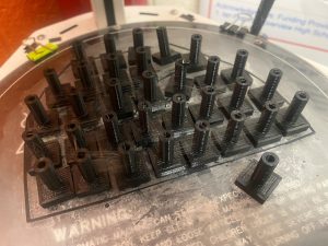
There is an important pedagogical idea here. If we had said, let’s learn to 3D print for the sake of 3D printing, it might be valuable in the future, we would not have buy in. There are other things to do. Remember, this is all happening at lunches and after schools with other homework and distractions going on. However, because we need these pegs, it is an opportunity to learn 3D printing.
Ring Testing: In a hurry to get as many rings as possible for the presentation, we did not glue all the rings and after moving some rings around, and some near misses with feet, we are no longer sure that all the rings are working. In addition, we are considering snipping off half of the ground and 5V wires to adapt from a series power circuit to a parallel manifold circuit. Each ring would need to be retested. Now we have different students learning the puzzle solving and of course, now we have more soldering to do. It looks like we will need to order some new segments. We have 3 or 4 segments that seem to have corrupted data lines because the change colour part way through the segment, but that is not in the code. A couple others have lost their DIN or DOUT pads. We need to order these ASAP.
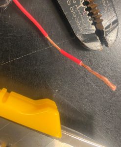
Manifold Power Supply: We are making manifold parallel circuit power supplies. We had a bit of 18 gauge speaker wire from LEO that we are using. It is easy to cut some of the strands as we try to remove insulation. We also wondered about 14 gauge solid core house wire. The larger gauge will reduce the resistance. How much gauge is needed?
There seems to be no noticeable issues using the 18 gauge. The wires do not seem to be warm at all.
However, it was suggested that we go to 14 Gauge. It is much easier to remove the insulation, but it is much harder to solder. It appears that the heavy gauge wire does not warm up enough to adhere to the solder. Even using a 60 W heavy soldering iron, we get cold welds. This whole thing will rotate. The solder connected one side of the wire to the other, but did not connect to the heavy gauge. Perhaps the 18 Gauge is a better choice!!
Ring Placement: Should we have the rings in nice straight columns? the Carbon chains of organic molecules are placed in a row in elementary studies, but quickly becomes the familiar zigzag that better represents the sp3 hybridization. Is there something similar for DNA? It appears as though the center ring should be offset a little bit so it forms a bit of a V shape.
So our columns need to be v-shaped a little bit. But should the columns also be off set a bit?
How many Nucleotides make a complete twist? Sounds like something between 9 and 12 depending on the type of DNA.
N’s Creativity: “N” had not shown much interest in the project until today where he really participated. He said that if it was going to represent DNA, it should not be perfectly aligned into columns and rows and it should look like DNA. He tried to figure out how the hour glass shape might translate to our situation. I am not sure he considering that the hour glass shape of the DNA shape and the changing distances of the nucleotides is trying to show perspective and that they are not really longer or shorter, at least to that degree. This caused him to look at some other cool ideas. It as fun to hear the “vets” explaining to N the science that was already incorporated. He is looking to add his own science dimension. It was WAY FUN!!
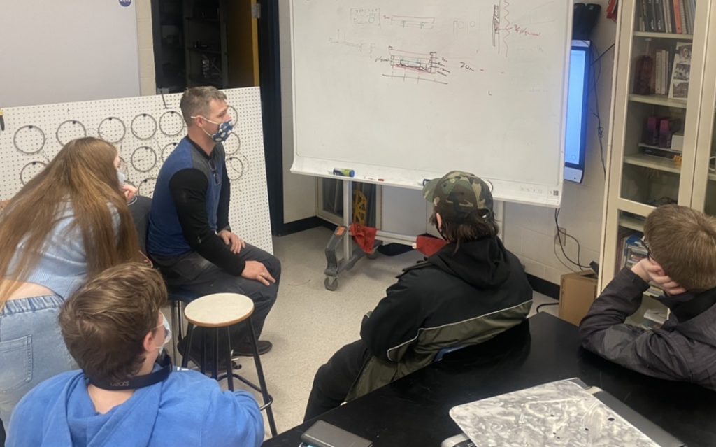
Visit from the Shop
Time to start thinking about the details of mounting to the wall. Mr Leaman visited from the shop to talk about how cabinets are often mounted to nicely distribute the weight.
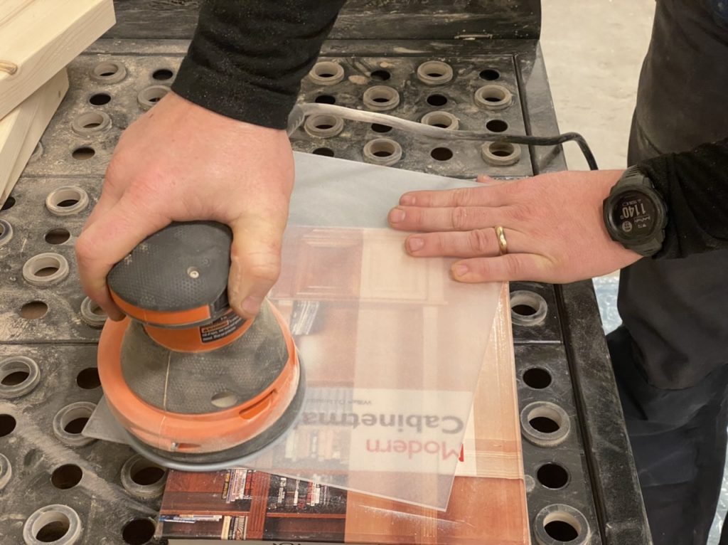
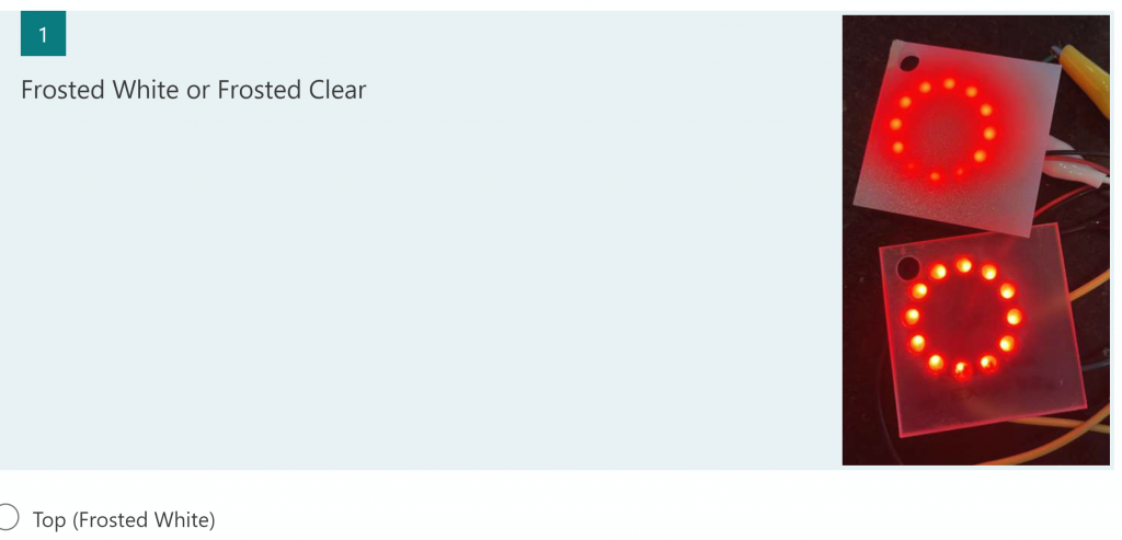
Later, we went to the shop to frost some clear acrylic. Will we like the crystal clear or frosted?
December Holidays We took a break over the December holidays followed by a COVID shut down. Despite these delays, progress kept going. We received a shipment of replacement ring segments. At long last we have our 3×9 matrix of rings! They have been test individually. We will wait for a while until we are back face to face to connect all of them together.
Dr Gurgon from DePauw University
How shall we arrange the rings? Should they be in nice straight columns and rows? Should there be some variations? Matching the science and artistic license, we can do almost anything we choose, but the choice should be informed, thoughtful and deliberate.


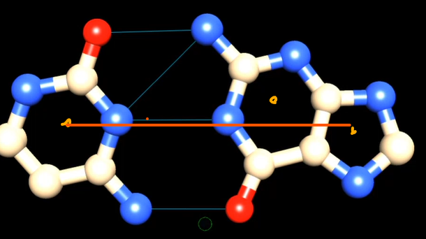
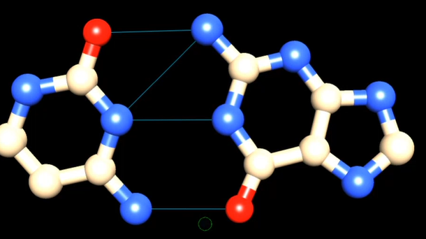
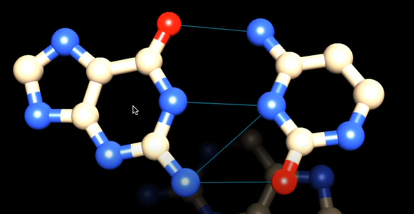


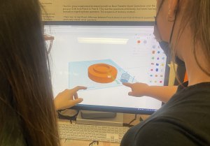
Daniel showed us some details of a 9 base pair of DNA in a 3D virtual environment. What geometries can we find? It take a little more than 9 base pairs to finish a rotation. But the center ring is slightly out of alignment to the other two. So rather than nice straight columns, perhaps it should be a nested V shape like a sergeant’s stripes.
Pandemic Lockdown Mini DNArt
We acquired some 12 LED rings so that we can play with the placements of the rings, and during the lock down, students can play with the code.
Bohr vs Schrodinger Atoms
Bohr though that electrons traveled in well defined orbits which would give atoms a very crisp edge that looks more like a ball. However, when you combine Heisenberg’s Uncertainty Principle with Schrodinger’s wave equations, the atom becomes more like a probability cloud with fuzzy edges.
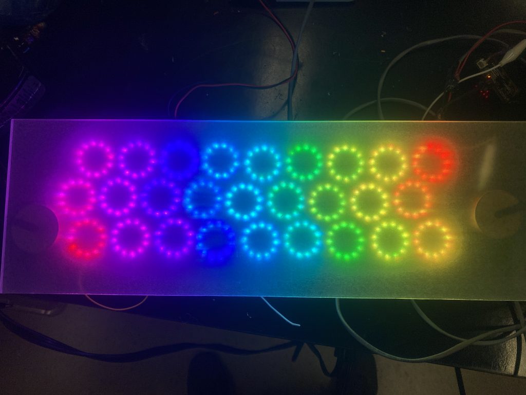
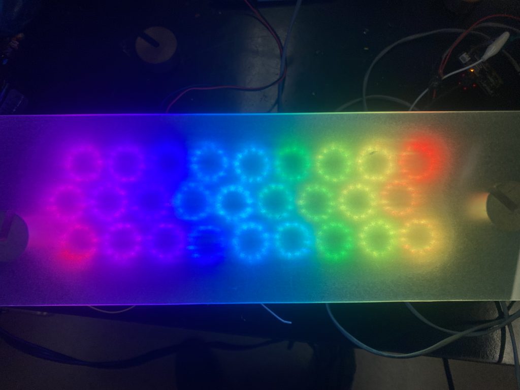
We have an opportunity to showcase one atomic model over another. It does not really matter which one we choose, but we should be deliberate in making that choice. This is where the aesthetics may dictate which model we choose to showcase. Which one do you prefer?
March Madness Artistic Democracy
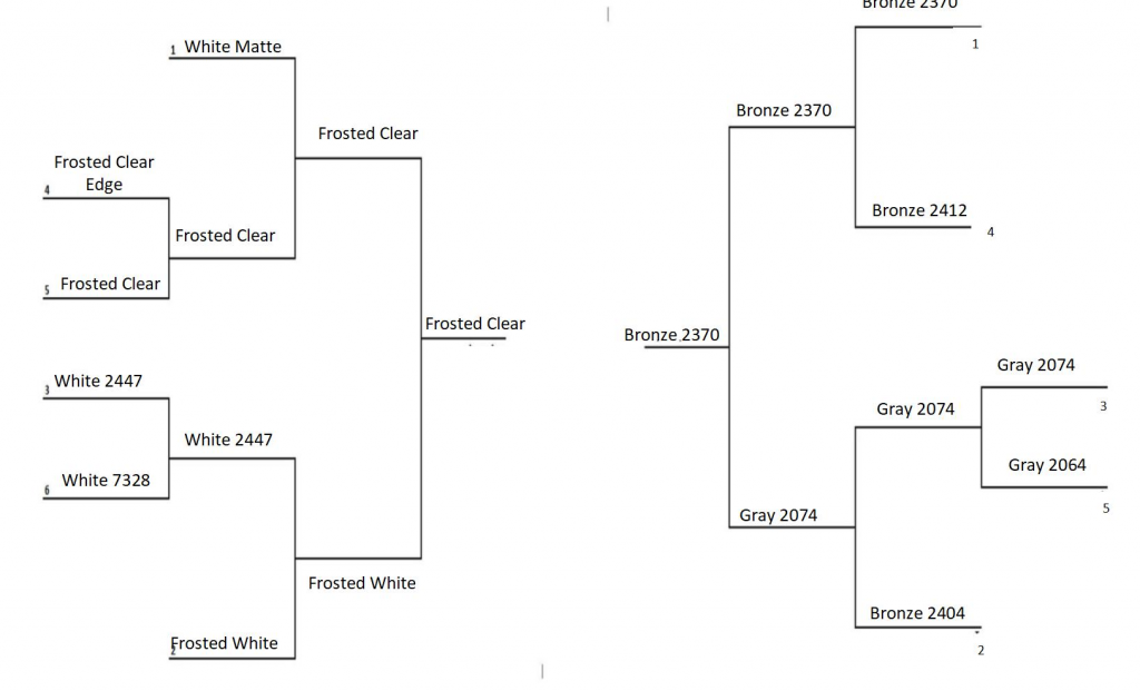
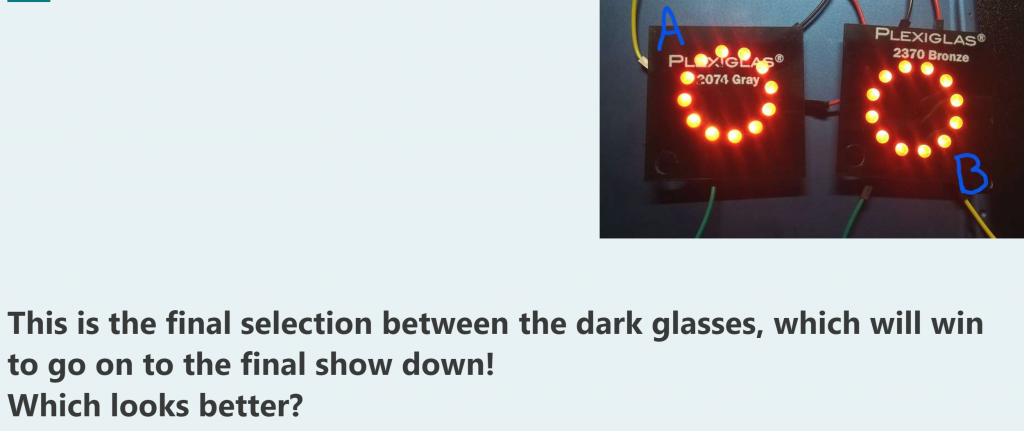
We have some choices to make. We need a cover for the lights. We have 11 choices ranging from of semi opaque white, clear, frosted, bronze, and shades of grey. Students set up a bracket system for head to head competitions like March Madness. While in lockdown, students took pictures of one versus another. the classes voted and the next day the competition continued. Since picture are not the same as real life, and the announcement that we will be back to F2F learning, we will wait for the final head to head to make a final decision.
LIDAR testing
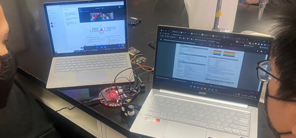
We are nervous that the range of the ultrasonic sensor is insufficient. Luckily, we had a LIDAR from a previous student project from 6 years ago that we can poach. However, this brings a new issue. We do not have a block or programming for LIDAR in Microbits. “I” and “R” are coming into this project cold. They spent some time comparing Arduino codes for both the ultrasonic and lidar sensors to see their commonalities and differences. Perhaps they can just edit the Ultrasonic sensor block for the Microbit? Now that means they need to talk about memory addresses etc… So in the middle of class, I reach out to Josh at Brilliant Labs and of course, he drops whatever he was doing and spent 1.5 hours with the kids walking them through things. Some of it the students could do, some of it needed some tweaking on the Brilliant Labs side. At the end of the 1.5 hours, we can measure distance!! Super awesome!!
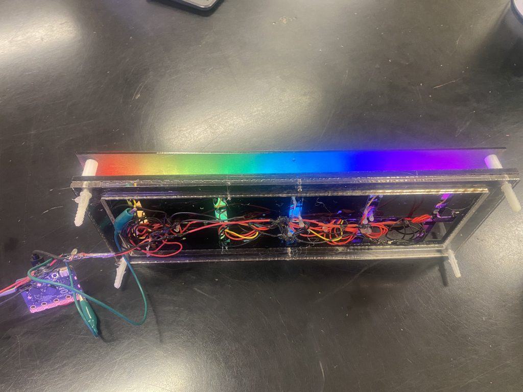
Little DNArt
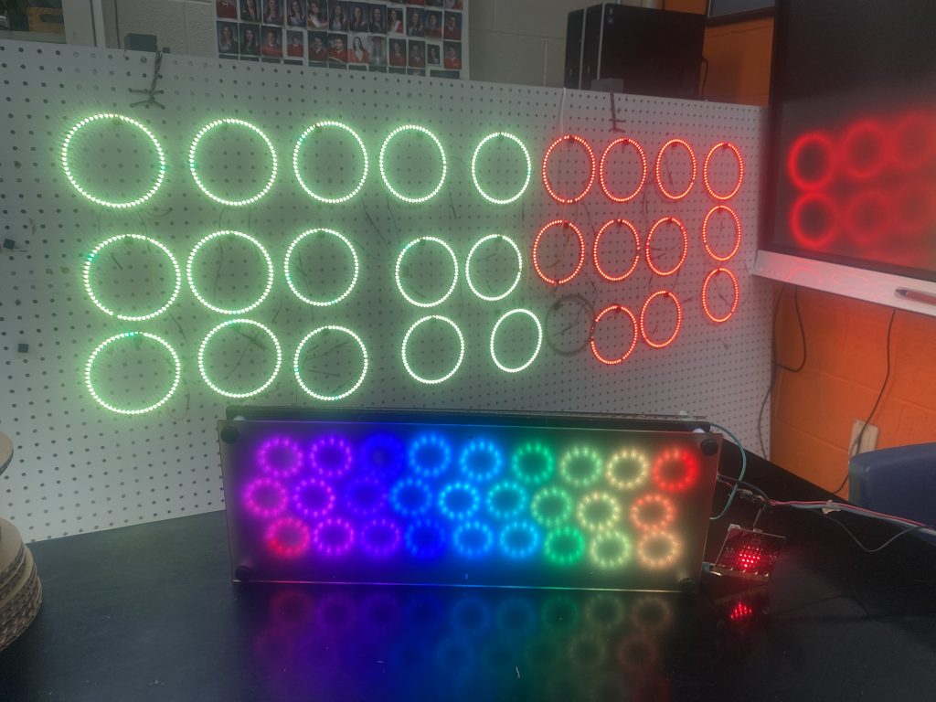
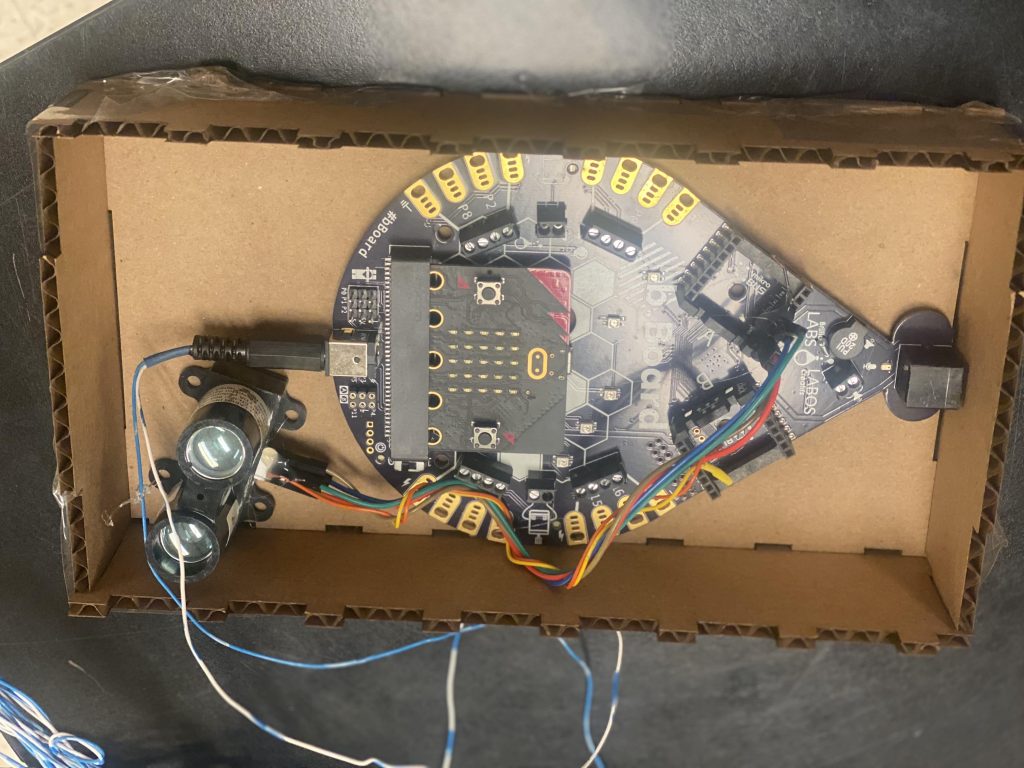
Our small model of DNArt is completed with the install of the microbit and ultrasonic sensor directly soldered into the power supply. We have a Bronze Acrylic cover. In the background are the larger 60 LED rings. Now if only the interruptions from Snow Days would stop!
Construction Begins
The rings were removed.
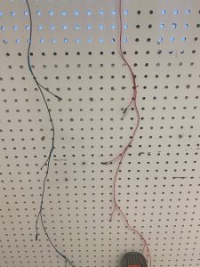
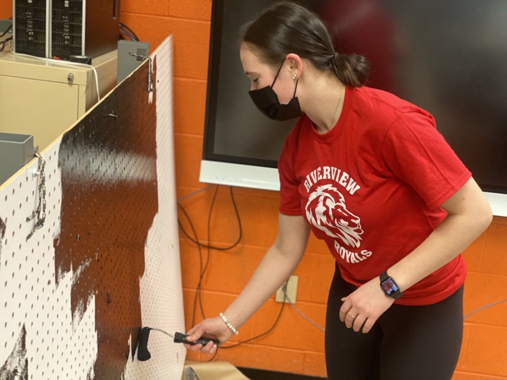
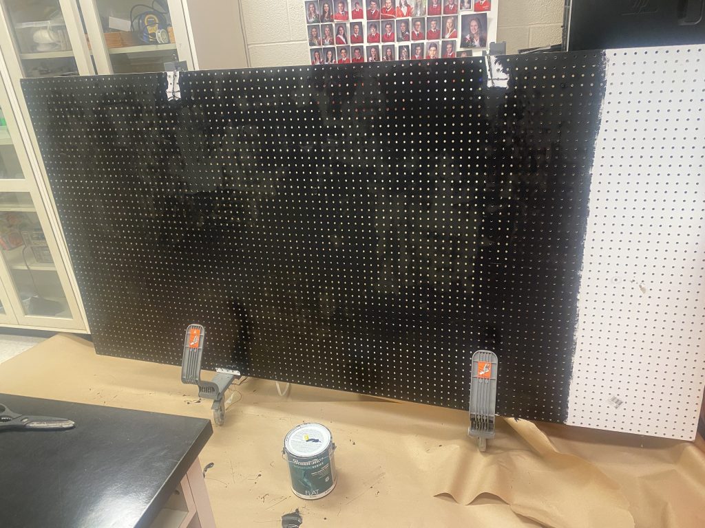
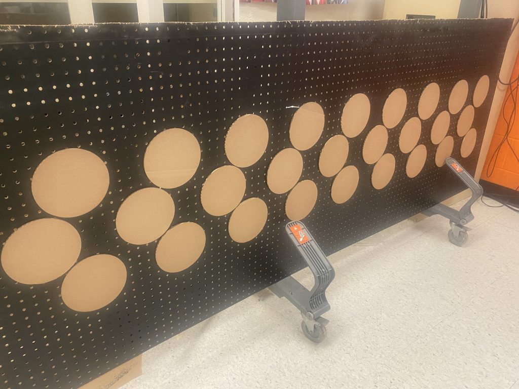
The Pegboard painted black
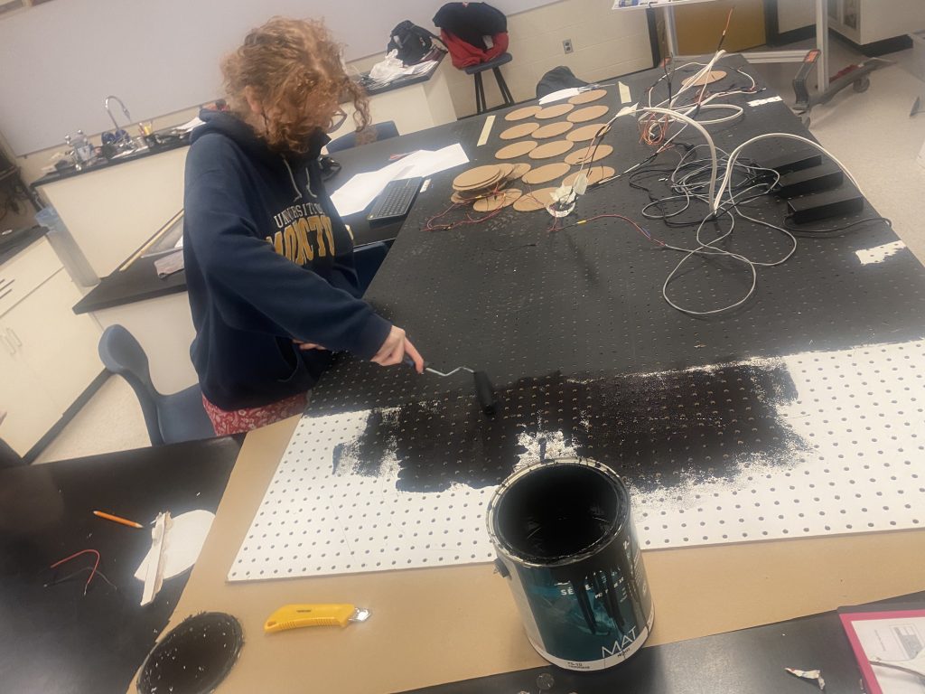
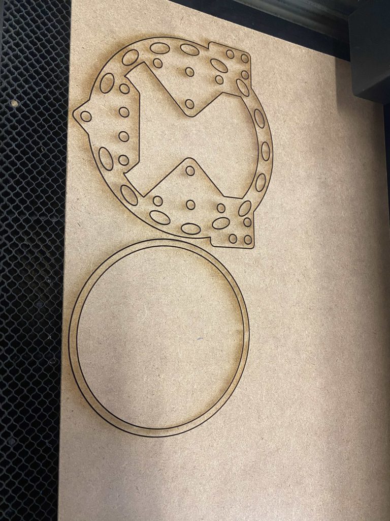
We used a laser cutter to make cardboard place holders for the rings.
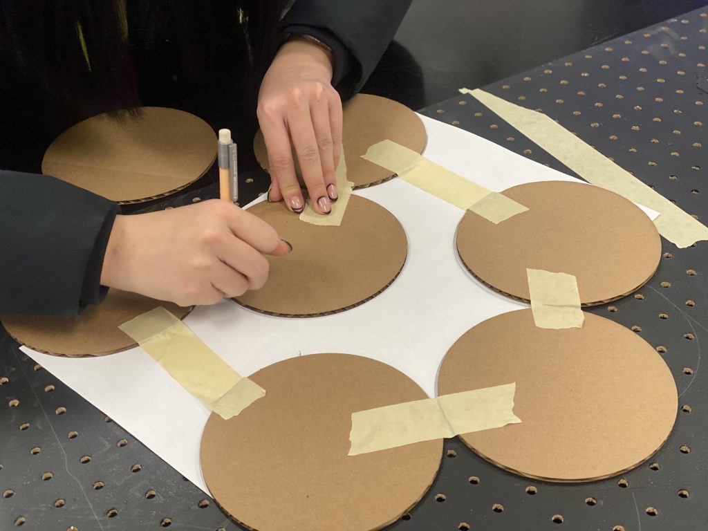
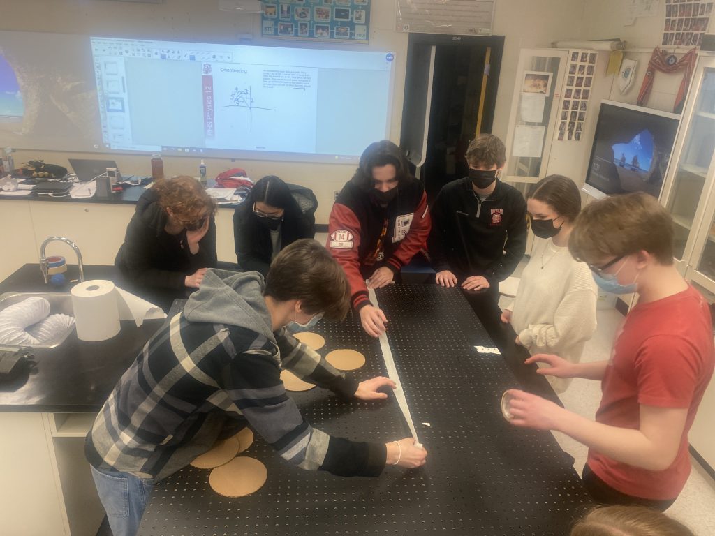
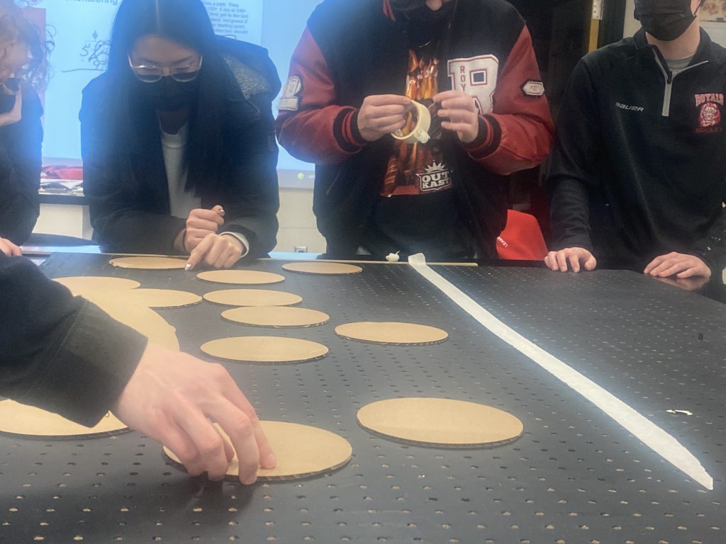
Students argued about the dimensions and the pattern, What looks nice and what is consistent with science? What rules can we break and which ones do we want to keep? For instance, we want to keep the basepairs in three rings. However, because in one moment, any group of 3 could be an A-T pair and then a moment later a T-A pair, we had to keep the spacing between the three rings consistent. However, we also remember the angles from the talk that Dr Daniel gave about the V shape. We are not going to try and measure it, just illustrate it, so we took some liberties with the angles.
The code is still not working quite right. It is difficult to see that a particular base pairs moves left or right.
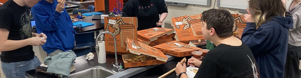
Josh from Brilliant Labs came to RHS for the day. He worked with our students to ponder how the coding of the DNArt can be made more efficient. They stayed all school day and well into the evening. We left around 9 pm, long after the pizza ran out! And, Victory!!! The code works nicely in the mini-DNArt.
The placeholders are in!! It is starting to take shape.
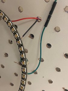
The first few rings are hot glued to the peg board.
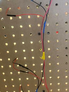
Hot glueing the jumper cables together as rings get added.
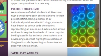
Featured by Brilliant Labs
We were featured in the winter Newsletter for Brilliant Labs in both English and French.


Electrical Work is in!
Robert, our wonderful electrician placed 4 plugs just behind the gyprock over the lockers, but had to run exterior conduit beside my room to get power.
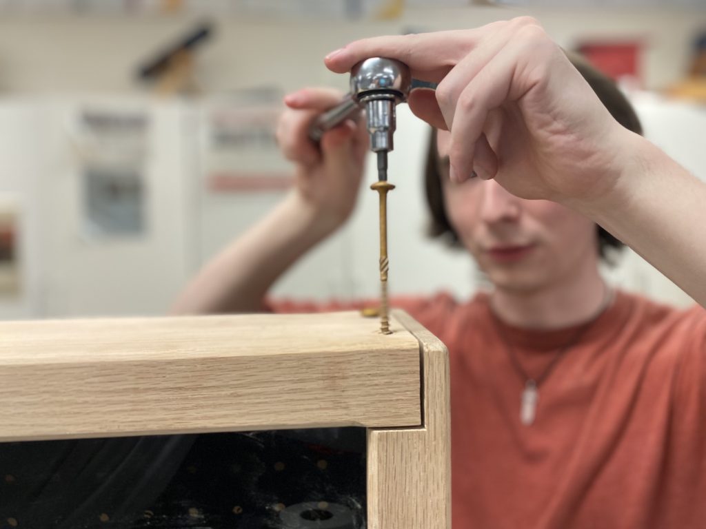
The Art of Joinery
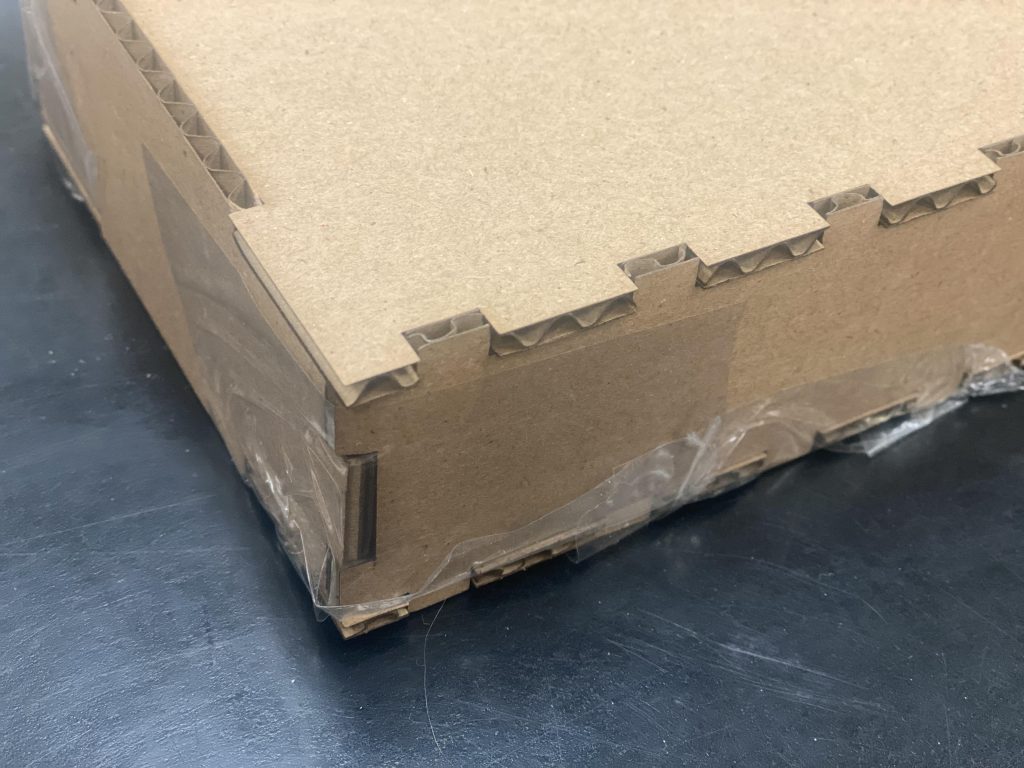
We used the laser cutter to make interlocking joints to create a box. Now that the card board model is done, we can move to acrylic. We were worried that the acrylic would block the LIDAR signal, as the IRProximity Sensor does for LEO, but it worked fine.
Are Done??…Nope 🙁
Look at the great OAK frame that our show class made along with the acrylic LIDAR case. There are only a couple days of school left. Are we done?
NOPE!, we are not. Se see glimmer of hope, but then something goes wonky and we do not know why. This is going to have to wait until next year!! Click here to see the video.
Year 2 (2022-2023)
Last year we were so close to finishing. Lots of learning, lots of chaos. There are to major symptoms. #1. The animation does not flow nicely from one side to the other. It flickers, and it is difficult to see how the base pairs are moving one way or the other. #2. The colours are inaccurate sometimes. When it is supposed to be all one colour, sometimes it is and sometimes it is not. There is something wrong that the signal does not consistently make it to the other end.
Let the investigation begin.
Weak Connections?
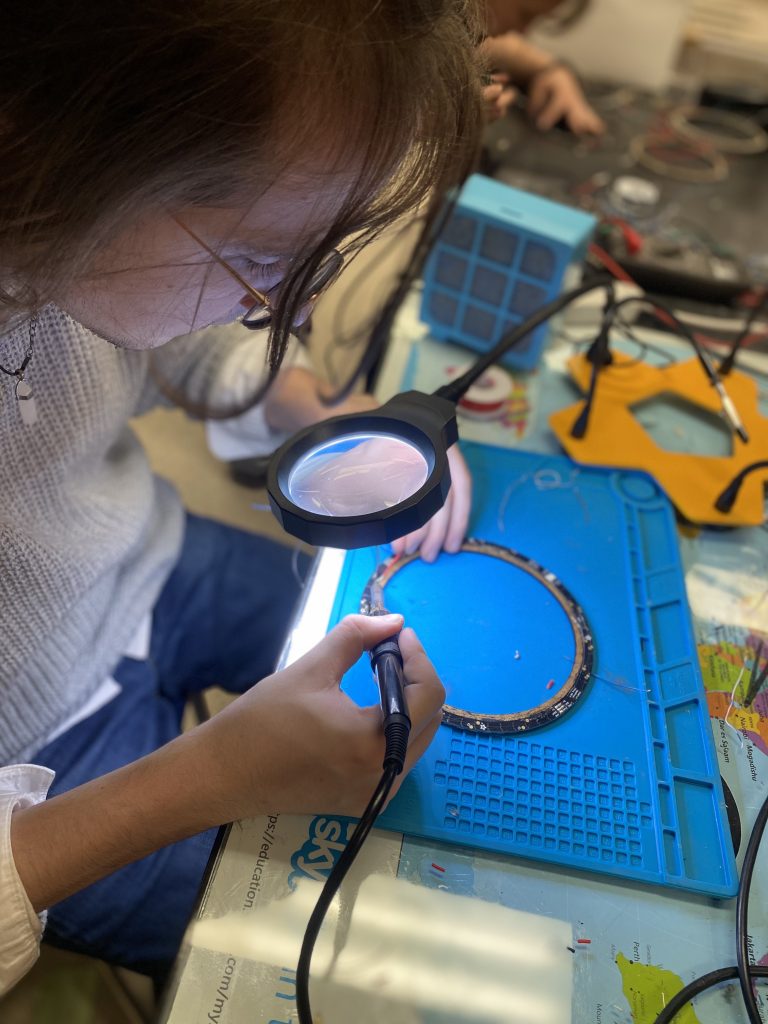
Josh from Brilliant Labs visited for a Tuesday evening to help us diagnose. We are just using the jumper wires, and is some cases it takes 3 or 4 wires to make it from the bottom to the top. Perhaps some of the gremlins are due to loose connections? Let’s solder every single wire connection. Lots of hands and first time solderers got the job done in about 2 hours on a Tuesday evening.
Click Here for Video http://foggs.ca/wp/wp-content/uploads/2023/01/DNArt-Solderign-Mess-xs.mov
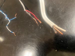
It is still causing problems. We need to investigate the connections to the rings themselves. That means taking off the front panel. It is a step we do not want to take, but here we go.
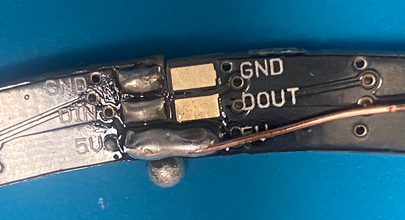
The connections between the ring segments need to be fixed. The non-leaded solder does not seem to wet, surround, adhere nicely to our jumper wires. During the process, we had to heat the pads a bunch and may have lifted some of the pads off the rings. We need to resolder EVERYTHING! NO!!! But that means it is an opportunity to clean up the electrical connections.
Josh tries to pull off individual neopixels to replace some of the burnt out ones. We are trying to bring signal and power to other LEDs with fancy intricate shunts.
Tuesday Evening Habits
Every second Tuesday evening, Josh travels from Freddy to Moncton. Kids work. We order food, kids work some more.
Platform Needed
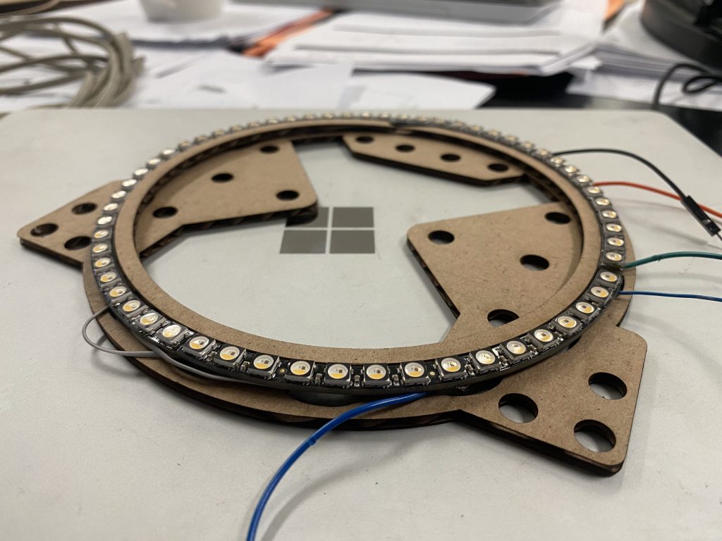
But as we work and move around, the connections are too fragile. We need a platform that can secure the work. We had an inner ring and a platform.
New Rings
We saved as many rings, and Frankenstein-ed others, but there were many that were not salvageable because of the lifted pads etc…. Josh generously ordered new ones.
#1. Voltage Shifter
There are a couple of possible fixes for the inconsistent signal. The Microbit is sending out a little over 3V signals over a large number of neopixels. They really would prefer 5V. Perhaps we need a voltage sifter to boost the voltage from 3 -5 V. Might as well order a couple of those too.
#2. Coding Issues
Perhaps there is a way to clean up the signal by changing the number of bytes that are being set to the neopixels. Perhaps this will smooth out the simulation.
New Wiring Patterns
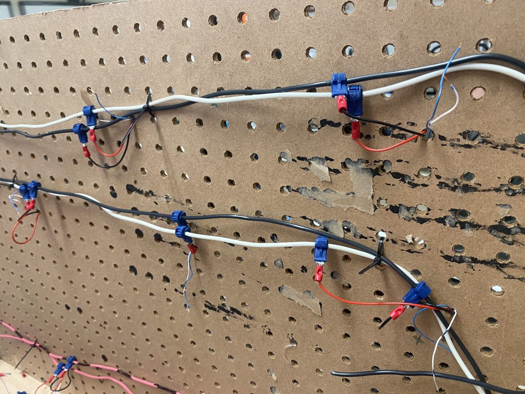
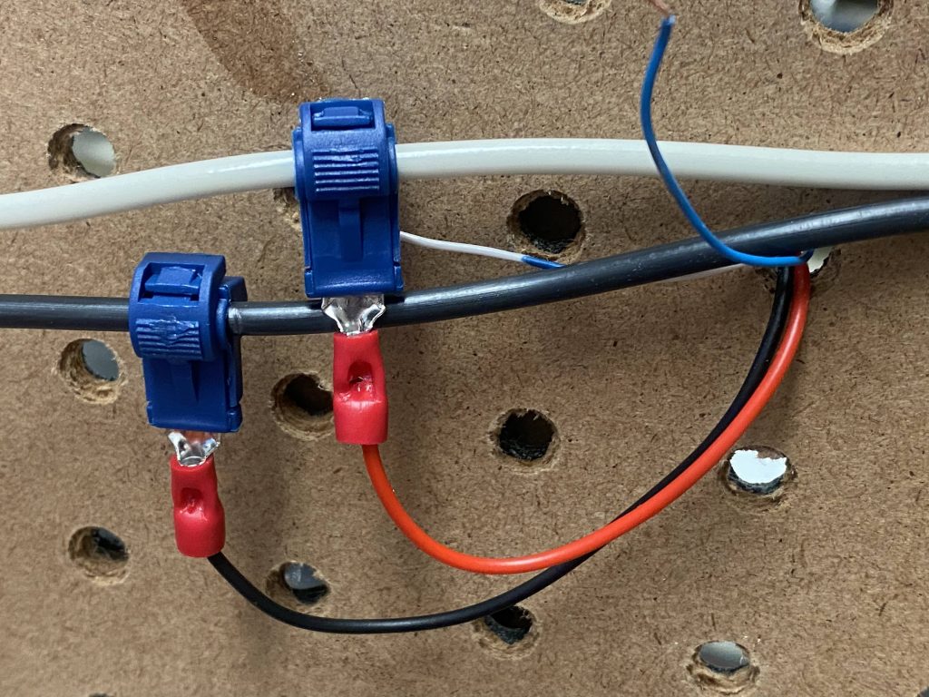
Now that the rings are glued to platforms and tested, we now have a modular system that means we could pop one ring in and out as needed. It would also be nice to have a clean and modular system for the wiring as well. Taping to the rescue. What if we ran three power and ground rails along the back of each ring and then used taping connections with spades. No soldering, no striping wires, and if it needs to be replaced, they just unclip. THIS IS SO NICE AND CLEAN!
Time for the test!!!
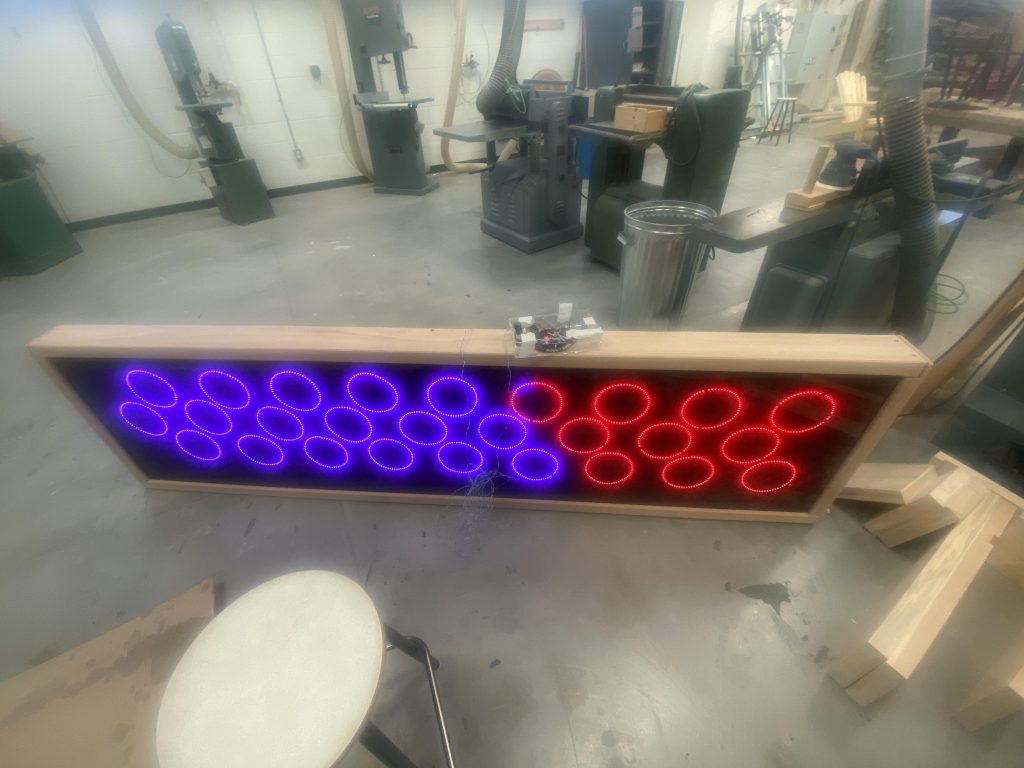
A year and a half of anticipation and ….so close. But the modular system shows its advantage directly, we can simply pop a single ring in and out without worrying about loose connections. The signal wires are just alligator clips at the moment until we are convinced, then we will solder them.
Click here for video. http://foggs.ca/wp/wp-content/uploads/2023/01/DNArt-w-rails-and-full-light-up-XS.mov
One of last year’s alumni is now at Carleton doing Comp Sci. He came back for a short New Year’s visit. Does he go and hang out with his folks? Or perhaps meet up with his friends? No. at 4:30 pm on Dec 31st, he walks off the airplane, rents a car, drives directly to the high school, works away on the code so that now the MINIDNArt with an ultrasound and a remote microbit seem to be working. He stayed until 7 pm on New year’s Eve. What does this show about engaged learning?
In theory, we should also have to make a few changes to the larger DNArt and that will also be working. I am not so happy about the range with the ultrasonic sensor. I would have expected a range of about 2-3 m. That does not seem to be the case. That is a later problem.